Hi rabbitz
thanks for your hint but i go for 18-0-18 and these transformers are on my bench,
i did a 6 hours test with my aliexpress kit with 100mVrms sweep , 25Vrail 8R load ....its about 2,3Vrms output....0,7Watt......the chip gets stable with 46°C all the time....so for me this fake is a TDA2050.
now i test the second ali kit (from my son) and it worked with 25V per rail too.
test is ongoing.....running at 46°C stable...
DC offset is 0,1mV !!!
chris
Ali kit 2 (my sons kit)
yes this chip is stable at this low power over night = 14hours with 46°C on the chip. as short power test with 300mVrms in give me about 5,1W att at 8R and the heat rapidly ( 2 min) goes up to 83°C !!!....not good...STOP!
hmm...maybe the chip can handle 25Vper rail but its "die" is too small = fake....
i did a following test - my idea is tho push 4 Watt - this is a good home use power - into 8R an see what happened
- input 250mVrms 1khz, scope 5,5Vrms ...3,7 Watt
with 25Vper rail i got after 5 minutes 78°C on the chip (starting with 30°C)
then i cooled down to 30°C again and set the rail voltage down to 20V. with - input 250mVrms 1khz, scope 5,5Vrms ...3,7 Watt after 5 min i get just 55 °C.
cool down to 28°C and 18 minutes the test again ---> 58°C
so the chip on my sons kit worked better (not so hot) at 20V rail - with the same output power.
will do the test with the ali kit 1 ..
chris
Last edited:
Ali kit 2 (my sons kit)
yes this chip is stable at this low power over night = 14hours with 46°C on the chip. as short power test with 300mVrms in give me about 5,1W att at 8R and the heat rapidly ( 2 min) goes up to 83°C !!!....not good...STOP!
....................................................
chris
Hi Chris,
Good to hear that it is now a father&son activity. I started at 11 as well.
My experience with the perhaps fake LM1875s is that when they suddenly get very hot, it is because they start having stability problems. The extra heating comes from oscillation around 1MHz.
Check the output signal when you increase the voltage rails and output amplitude. You may see the same effect as I.
You have a good size heatsink on the LM1875s for a start?
FF
Hi FF...welcome here..
i stopped the Class D and start to learn more about chip amp
ok.scope is the next topic...
heatsink is this 2,3K/W just to have something to test...is it too small to push short or do my endurance tests . e.g 100mVrms = 2,3Vrms into8 R = 0,7 Watt??
%product-title% kaufen
chris
Chip-amps also offer very good sound. The problems are somewhat different than for class D. Class AB has a varying loop-gain that is supply voltage and output level dependent such that various self-oscillation phenomena are an issue. Always keep the power transistors well cooled, for a start with a good fan and a heatsink. An advantage of class AB is the lack of output filter such that the class AB amplifiers can run without load, which is very useful for test. The bandwidth of class AB is typically higher than for class D amplifiers and you can make composite amplifiers. You (and your son) will see.
As I understand, you have fixed +/-25Vdc rail voltages. If your LM1875 behaves like mine (mine also got terribly hot at a moment) there is an important test to do. It relates to self-oscillation and stability. Use a fan to cool the heatsink.
Put your oscilloscope on the amplifier output and start with a 16 Ohm resistive load. When you increase an 1KHz sine-wave input signal from zero amplitude, can you reach clipping at the output without the sine-wave looking strange (only clipping of course)? If OK with 16 Ohm, try with 8 Ohm. Still possible to reach clipping? Then try with 4 Ohm, still OK?
My experience is that with higher supply voltages and lower load impedance, the LM1875 tend to "collapse" with the sine-wave at certain output level. You see it as an asymmetrical and not clean clipping of the output signal. During this clipping, you will notice HF-oscillation. That is the moment when the LM1875 becomes really hot. Endurance test is of no use with self-oscillation.
Last edited:
Hi FF
let me summarize.
so you mean that i have to go as near as possible to my rail voltage, e.g.+/- 25 = 50V peak to peak with 8R. so as less voltage i get the chip is more "busy" with oscillating?--> getting hot without give more power
8R load:
this is done - and failed at #113 - i get 42,5Vpp max at 50V - 25V rail
https://www.diyaudio.com/forums/chip-amps/341675-ebay-mono-lm1875-kit-12.html#post5916540
is done and failed at post 120 with 18V rail - 36V i get 29,9Vmax
its done post 123 with 20V rail = 40V and failed at 33,5Vmax
its done post 127 with 25V rail = 50V and failed at 39,1V
is that what you mean?
chris
Hi FF
let me summarize.
so you mean that i have to go as near as possible to my rail voltage, e.g.+/- 25 = 50V peak to peak with 8R. so as less voltage i get the chip is more "busy" with oscillating?--> getting hot without give more power
8R load:
this is done - and failed at #113 - i get 42,5Vpp max at 50V - 25V rail
https://www.diyaudio.com/forums/chip-amps/341675-ebay-mono-lm1875-kit-12.html#post5916540
is done and failed at post 120 with 18V rail - 36V i get 29,9Vmax
its done post 123 with 20V rail = 40V and failed at 33,5Vmax
its done post 127 with 25V rail = 50V and failed at 39,1V
is that what you mean?
chris
Hi Chris,
Going through your previous measurements, I partly found an answer to my concerns. I understand that you can vary the rail voltages and use not only the 18V-0-18V transformer. I got confused by the attempts to guess what other chip was inside the LM1875 housing (TDA2030, TDA2040 or TDA2050). From what I see, it is likely to be LM1875 performance.
With 8 Ohm load, I see no sign of HF-oscillation up to 25V rail voltages on the photos you show. My problems started above 24V with 8 Ohm load (wire-wound power resistor with some inductance). Thus, your chip seems to perform OK. Another sign of a fake chip is its (in)ability to drive the output close to the rail voltages. Class AB cannot go very close to the rail voltages such as class D can. It is not a "failure" that the rails cannot be reached. The LM1875 datasheet tells us that with +/- 25V rail voltages and 8 Ohm load, the typical output power at clipping (about 1% THD) is 25W. 25W in 8 Ohm should be very close to 20Vpeak. With symmetrical rails 20Vpeak (one way) becomes 40Vpp total. You tell me that you measured 39.1Vpp which is within 40Vpp "typical". Still normal LM1875 performance.
Most likely you have an LM1875 chip inside - genuine or fake depends on the definition.
When the upper half of my sine-waves collapsed in HF-oscillations, the current control in the power stage is lost and current pass from the positive rail and down to the negative rail directly (and uncontrolled). That heats up a chip very fast.
Play safe for now and do some listening tests with eventually 22V rail voltages and a noiseless fan. Cooling is a matter of size, shape, position and surroundings. A solution can be found if needed.
If you after the listening tests want to investigate the chip further, test it with 28V rails and a 16 Ohm load. I guess you will succeed. Should you see the holy smoke, let me know and I will send you a letter with a couple of my LM1875 for replacement.
FF
Last edited:
Hi Chris,
Another sign of a fake chip is ....
That when the speaker outputs are shorted... it simply dies, instantly.
A Real one won't.. 'nuff said.
THE Acid kool aid test.
Good Morning FF
Thank you for you advise. after reading now your post again i understand clearly but you clarify in the second post. maybe it was too late yesterday
thanks FF to provide me some lm1875...its not needed...i have more then one kit from aliexpress. the only topic what is interesting for me is the THD graph of a real 1875 and the others....the real lm1875 seams really good...and therefore i expect a better sound
@bare
the short cut test i don´t do yet...but is i read its mandatory to be sure if its a real one.
chris
Last edited:
short cut test...
Hi
i did the short cut test at one example each kits....
- the TDA= fake 1875 died immediately and my lab psu shows 2A at both rails and the voltage protection kick in.
so the aliexpress kit are what ever...
-the amazon kit survived this test !!! 5 times without a problem
chris
Hi
i did the short cut test at one example each kits....
- the TDA= fake 1875 died immediately and my lab psu shows 2A at both rails and the voltage protection kick in.
so the aliexpress kit are what ever...
-the amazon kit survived this test !!! 5 times without a problem
chris
Last edited:
That when the speaker outputs are shorted... it simply dies, instantly.
A Real one won't.. 'nuff said.
THE Acid kool aid test.
True, that test I haven't performed.
@chermann:
You have the guts! Want some replacement LM1875s? Your scope, I believe, can do THD but only very roughly. You can use your soundcard and Arta.
Last edited:
psu...cap bank
Hi Bare, Rabbitz, FF
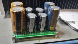
i build caps bank with 10, 000µF per rail -i use that what i have at home
gold nichicon UFW 3300/50V
black panasonic FC 2x 2200µF/35V
blue panasonic FC 1x 3300µF/35V
i want to make a CRC filtering e.g.
3300 gold - 3x 1 R / 3W the 2x 2200 black +1x3300 blue
bleeder resistor between + and GND 2k2 1W ...and - and GND 2k2 1W
or is it better to use: CRC
3300 gold - 1x 2200 black - 3x 1 R / 3W the 1x 2200 black +1x3300 blue
bleeder resistor between + and GND 2k2 1W ...and - and GND 2k2 1W
or should i turn around. i mean the panasonic blue is faster an it should near the transformer??
pic 1 is my cap bank
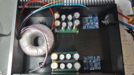
pic 2 is the actual planning in my housing - its getting tight
thanks
Hi Bare, Rabbitz, FF
i build caps bank with 10, 000µF per rail -i use that what i have at home
gold nichicon UFW 3300/50V
black panasonic FC 2x 2200µF/35V
blue panasonic FC 1x 3300µF/35V
i want to make a CRC filtering e.g.
3300 gold - 3x 1 R / 3W the 2x 2200 black +1x3300 blue
bleeder resistor between + and GND 2k2 1W ...and - and GND 2k2 1W
or is it better to use: CRC
3300 gold - 1x 2200 black - 3x 1 R / 3W the 1x 2200 black +1x3300 blue
bleeder resistor between + and GND 2k2 1W ...and - and GND 2k2 1W
or should i turn around. i mean the panasonic blue is faster an it should near the transformer??
pic 1 is my cap bank
pic 2 is the actual planning in my housing - its getting tight
thanks
Attachments
Last edited:
Firstly ESP P72 recommends 2 x 4700uF for 2 channels and maximum of 2 x 10000uF.
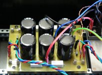
The power supply that I have used successfully with AKSA 55N+, BAKSA, P101 and NXV200 uses 6 caps, 1 transformer and 1 bridge rectifier. For 50W amps I used 6 x 4700uF and for 100W amps I used 6 x 10000uF.
The +/- from the bridge rectifier goes to the centre 2 caps > 2 0R1 5W resistors each side of the centre caps > 2 caps each each end. Each end supplies 1 channel only so it acts like a pseudo dual mono supply. The transformer CT goes to the centre of the board as well as chassis ground and if required, speaker ground also connects to this point.
Disregard the by-pass caps as it was a trial and no bleed resistors were used but I did have LEDs on each rail.
Not my design but from a reputable source.
Attachments
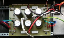
So what I am suggesting is use only 1 of those power supply boards, spin 90° and place in between the amp PCBs and midway between the transformer and amp PCBs. This way each side of the power supply goes to 1 channel directly. Using your existing caps, use FW on the outsides (4 caps) and FC on the inside (2 caps).
The +/- from the bridge rectifier goes to the centre 2 caps > 2 0R1 5W resistors each side of the centre caps > 2 caps each each end.
Looking nice Rabbitz!
I wonder what the 5w resistors are for? I haven’t got these in my setup.
/Kurt
So what I am suggesting is use only 1 of those power supply boards, spin 90° and place in between the amp PCBs and midway between the transformer and amp PCBs. This way each side of the power supply goes to 1 channel directly. Using your existing caps, use FW on the outsides (4 caps) and FC on the inside (2 caps).
Hi Rabbitz
i just joking
... i rectifier and 1 cap bank is enough sorry for that....
your pcb is interesting...so i understand that its in the middle there is the "source" /center = first caps in the middle (cap No.2) and to every side the R 0R1 5W and the the next cap...
but
this comment ....i do not understand...FW on the outsides (4 caps) and FC on the inside ....sorry
chris
Looking nice Rabbitz!
I wonder what the 5w resistors are for? I haven’t got these in my setup.
/Kurt
with the caps -resistor - caps you build a CRC "Filter" - to get the ripple voltage of the supply down ...
here...i want to show you a diagram and found a pcb (kit)
ZEROZONE Dedicated CRC power supply board 8*22000uf 35V PSU board for PASS-in Amplifier from Consumer Electronics on Aliexpress.com | Alibaba Group
chris
- Home
- Amplifiers
- Chip Amps
- eBay mono LM1875 kit