Chris, this shows perfectly what a huge capacitance 100pF can be at the right place. Very nice.
What we all can learn from this, the more refined an amp gets, the more the PCB design matters, as an connecting trace is a capacitor. So even if two amps share the same schematic, thy might not perform identical. These are, in the end, some of the causes for very fine differences with amps.
It is worth nothing, that there are very good sounding amps, that totally deform a square signal. This is one aspect of an amp, only. One can not say this often enough.
Would be interesting how pic. No. 4 sounds with music if you make the capacitor switchable.
If you look at the block diagram of this chip, you see with pin 1+2 you are directly and unprotected at the base of the first transistor pair of the inner circuit. If I was to use this chip as an amp, I would put an input buffer in front of it, to secure stable conditions at this critical point. Then optimize or experiment.
In fact, you are doing this already, as your generator has an output buffer.
The downside, even if you tune the chip to perfection, the moment where you remove the generator and put another source (music maybe?) in front of it, all the optimization is put in question.
PS I would go with FF and use a 600-5000 Ohm resistor over the pins.
Last edited:
Hey all, just a quick update about my darn HDMI adapter, I noticed if I pull the safety earth I don't get the HDMI adapter noise (also this noise is louder when the screen displays a lot of white! Funny everything you can test while confined...)
So for the HDMI, I now know there is something wrong once I plug in the earth, but I will get back to this later. Makes me wonder why I even need it when all my equipment doesn't have a safety earth connection...
I do still get what I think is induced hum from speaker wires proximity with the 120v lines (only on the left channel, so its what makes sense to me so far). It is very subtle, but there when I put my ear to the speaker.
Following turbowatch advices I decided to twist the speaker wires I already had in there, it didn't seem to fix it, maybe it helped, but its getting hard to follow")
I have some shielded wire, so I will give this a try soon. It would be nice to have it completely silent.
Protection board : the humming I get from the board itself (not the speakers, the board itself was emitting sound) stopped when I gave the board a lower, and independent, power supply (12v instead of 27vdc or so IM getting out the PS board). For now its using a very common wall-wart thing... so I will have to come up with a solution for that too, probably another small PS circuit.
Thanks,
So for the HDMI, I now know there is something wrong once I plug in the earth, but I will get back to this later. Makes me wonder why I even need it when all my equipment doesn't have a safety earth connection...
I do still get what I think is induced hum from speaker wires proximity with the 120v lines (only on the left channel, so its what makes sense to me so far). It is very subtle, but there when I put my ear to the speaker.
Following turbowatch advices I decided to twist the speaker wires I already had in there, it didn't seem to fix it, maybe it helped, but its getting hard to follow
I have some shielded wire, so I will give this a try soon. It would be nice to have it completely silent.
Protection board : the humming I get from the board itself (not the speakers, the board itself was emitting sound) stopped when I gave the board a lower, and independent, power supply (12v instead of 27vdc or so IM getting out the PS board). For now its using a very common wall-wart thing... so I will have to come up with a solution for that too, probably another small PS circuit.
Thanks,
If I can not find the cause for hum and think it might be induced from one part of the installation into another, I have an easy way of finding the right direction.
Get a piece of sheet metal, maybe from Campbells Tomato soup or Libb´s fruit cocktail. If you are in China, canned Pangolino or garlic spiced bat will do. It is only for the tin can. Eat what you like.
Connect a wire to the metal and put it into a plastic bag or wrap it with tape, whatever will work to prevent a short. Connect the wire to central ground.
Now, while listening to hum, you can put the sheet between different wires and over active parts. You will soon notice changes in the hum. This may give you a hint where to look for a solution.
Good luck!
garlic spiced bat will do
Mmmm... I love garlic!
Hahaha, thanks for the advices I will keep you posted.
Chris, this shows perfectly what a huge capacitance 100pF can be at the right place. Very nice.
......
PS I would go with FF and use a 600-5000 Ohm resistor over the pins.
Hi again
i try at a mono board at pin 1-2 the resistors what i have at home. not easy to hold the resistors and press at the scope the hold button
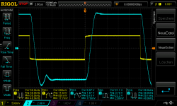
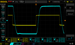
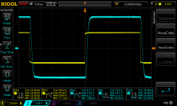
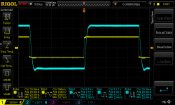
+/-22V supply , 4,459R load - square wave at 600mVrms in with 50kHz-about 17WAtt ---> fan used
What is the best response?
pic 1 22Vsupply 4,459Rload square 50khz 600mVrms_no resistor pin1_2
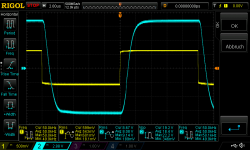
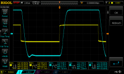
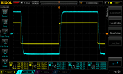
pic 2 22Vsupply 4,459Rload square 50khz 600mVrms_2k7 pin1_2
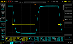
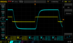
pic 3 22Vsupply 4,459Rload square 50khz 600mVrms_3k3 pin1_2
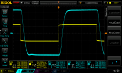
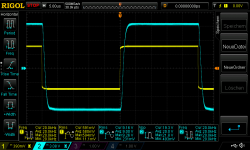
pic 4 22Vsupply 4,459Rload square 50khz 600mVrms_3k9 pin1_2
pic 5 22Vsupply 4,459Rload square 50khz 600mVrms_4k3 pin1_2
pic 6 22Vsupply 4,459Rload square 50khz 600mVrms_4k6 pin1_2
pic 7 22Vsupply 4,459Rload square 50khz 600mVrms_6k8 pin1_2..no that doesn´t help
thx
chris
Attachments
-
 22Vsupply 4,459Rload square 50khz 600mVrms_no resistor pin1_2.png45.4 KB · Views: 193
 -
 22Vsupply 4,459Rload square 50khz 600mVrms_2k7 pin1_2.png44.2 KB · Views: 192
 -
 22Vsupply 4,459Rload square 50khz 600mVrms_3k3 pin1_2.png42.9 KB · Views: 191
 -
 22Vsupply 4,459Rload square 50khz 600mVrms_3k9 pin1_2.png46.9 KB · Views: 190
 -
 22Vsupply 4,459Rload square 50khz 600mVrms_4k3 pin1_2.png46.2 KB · Views: 190
 -
 22Vsupply 4,459Rload square 50khz 600mVrms_4k6 pin1_2.png44.8 KB · Views: 44
 -
 22Vsupply 4,459Rload square 50khz 600mVrms_6k8 pin1_2.png42.7 KB · Views: 39
Last edited:
hi
just for completeness:
pic 1 22Vsupply 4,459Rload square 50khz 600mVrms_1k5 pin1_2
pic 2 22Vsupply 4,459Rload square 50khz 600mVrms_1k8 pin1_2
just for completeness:
pic 1 22Vsupply 4,459Rload square 50khz 600mVrms_1k5 pin1_2
pic 2 22Vsupply 4,459Rload square 50khz 600mVrms_1k8 pin1_2
Attachments

Hi again
i try at a mono board at pin 1-2 the resistors what i have at home. not easy to hold the resistors and press at the scope the hold button
+/-22V supply , 4,459R load - square wave at 600mVrms in with 50kHz-about 17WAtt ---> fan used
What is the best response?
pic 1 22Vsupply 4,459Rload square 50khz 600mVrms_no resistor pin1_2
pic 2 22Vsupply 4,459Rload square 50khz 600mVrms_2k7 pin1_2
pic 3 22Vsupply 4,459Rload square 50khz 600mVrms_3k3 pin1_2
pic 4 22Vsupply 4,459Rload square 50khz 600mVrms_3k9 pin1_2
pic 5 22Vsupply 4,459Rload square 50khz 600mVrms_4k3 pin1_2
pic 6 22Vsupply 4,459Rload square 50khz 600mVrms_4k6 pin1_2
pic 7 22Vsupply 4,459Rload square 50khz 600mVrms_6k8 pin1_2..no that doesn´t help
thx
chris
Hi Chris,
You can see that the higher the resistor value, the higher the bandwidth (more square-waved) but the less the damping. I would go for pic.5 (4K3) and try for a check how it looks at 10KHz with 4K3. 50KHz may be good for adjustment but is fully outside the range of even the best human ears.
as requested
pic 1 22Vsupply 4,459Rload square 20khz 600mVrms_2k7 pin1_2
pic 2 22Vsupply 4,459Rload square 20khz 600mVrms_3k3 pin1_2
pic 3 22Vsupply 4,459Rload square 20khz 600mVrms_4k3 pin1_2
Attachments
as requested
pic 1 22Vsupply 4,459Rload square 20khz 600mVrms_2k7 pin1_2
pic 2 22Vsupply 4,459Rload square 20khz 600mVrms_3k3 pin1_2
pic 3 22Vsupply 4,459Rload square 20khz 600mVrms_4k3 pin1_2
I would use the 3K3 or the 4K3. You can't hear the difference. The reproduction of a square-wave seems really nice and controlled.
When I have chosen a final resistor, I try sine-wave until clipping at 1KHz, 7KHZ and 20KHz to see that no oscillation or deformation appears at any amplitude and that clipping is regular and predicable.
When you have an amplifier performing predictably and stable in the whole audio range, it does at least sound good - perhaps very (very) good.
What is found to sound the best is highly individual and a higher level of distortion or less stability margin may be found to have a better sound-characteristic by some. We are engineers and have difficulty designing for individual appreciation.
If you use a power stage in a composite amplifier, you want the power stage to be an obedient and accurate slave of the OP-AMP (the master) such that the more predictable and stable the power stage is, the better.
Eventually try with 10nF or 100nF directly at the output to get an impression of sensitivity to capacitive loading. If not oscillating, I do the test at 10KHz and with a square-wave of around 40% of maximum amplitudel level.
If you feel like it, you can try the TDA2050 amp on speakers and see how it sounds compared to the genuine LM1875. Fred already did so. I am better at creating certain technical performance than judging on sound.
Good work!

Last edited:
Hi FF
Yes you are a very very good technician...i know.
as an ex audiophile ....for me its really not understandable that you "just" happy and go ahead to the next amp. i am looking up to you and other experience "DIYaudio champs"....with your technical knowledge you can do everything -->
You don´t want to hear your big knowledge full-filled in a "master peace" of amp? ...
...
thx
chris
Yes you are a very very good technician...i know.
as an ex audiophile ....for me its really not understandable that you "just" happy and go ahead to the next amp. i am looking up to you and other experience "DIYaudio champs"....with your technical knowledge you can do everything -->
You don´t want to hear your big knowledge full-filled in a "master peace" of amp?
...thx
chris
Hi FF
Yes you are a very very good technician...i know.
as an ex audiophile ....for me its really not understandable that you "just" happy and go ahead to the next amp. i am looking up to you and other experience "DIYaudio champs"....with your technical knowledge you can do everything -->
You don´t want to hear your big knowledge full-filled in a "master peace" of amp?
thx
chris
Hi Chris,
Many thanks for the kind words.
One day I will attempt my masterpiece of an amplifier. Turbowatch2 seems ready for his masterpiece but he is also much ahead of me with experience. When finished with the Triple LM1875, which I now see as an important development project but not as a final solution, and after having tested the LM1876/LM4766, I will try a stereo version based on the TDA2050. I will concentrate on an improved amplitude limiter for the OP-AMP. When that has been passed successfully, I may go for an LM3886 stereo version. Turbowatch2 knows that I, like himself, have many new projects waiting without end.
Among the clever words from Turbowatch2, I noticed the “engineerophile” who never reaches an end in his engineering activity but always carry on with new ideas. On a philosophical level there is a saying that “only those who dream may one day see their dreams come through”. In more plain operational terms - you need to have visions to have a chance of progress. The DIY-virus is stronger than any medical virus (which luckily are all temporary) and there will hardly be any cure for the DIY-virus. It forces us to fantasize about new improved constructions until time closes the final curtain. Chris, you are now infected with the DIY-virus and you are doomed - like us.

Last edited:
@FF you are right, like any DIYS victim, I still got some projects on the shelf.
Sometimes I collect parts for years, as I´m not in a hurry.
For example my active front and center HT speaker system needed 5 years to complete. The new sub woofer are in the planning for about the same time, now.
If you go for really good parts, a few years do not change a lot in High End HIFI. Some of the speakers I used 30 years ago, are still build today and belong to the best you can buy. When I replaced the old 1" Audax tweeter (Model year around 1990) with some new 30mm 90€ a piece items last year, the difference was there, but not ground shattering. Just important ( for me ).
I collect parts until the whole construction can be completed, then the assembly starts. Parts have to be what I want and what I´m willing to pay for them. I hate to get ripped off. Also I dislike doing things twice. This is hobby, not work and no one chases me to a finish.
Wish I had more time/ less health problems to do more practical (hobby) work...
Sometimes I collect parts for years, as I´m not in a hurry.
For example my active front and center HT speaker system needed 5 years to complete. The new sub woofer are in the planning for about the same time, now.
If you go for really good parts, a few years do not change a lot in High End HIFI. Some of the speakers I used 30 years ago, are still build today and belong to the best you can buy. When I replaced the old 1" Audax tweeter (Model year around 1990) with some new 30mm 90€ a piece items last year, the difference was there, but not ground shattering. Just important ( for me
). I collect parts until the whole construction can be completed, then the assembly starts. Parts have to be what I want and what I´m willing to pay for them. I hate to get ripped off. Also I dislike doing things twice. This is hobby, not work and no one chases me to a finish.
Wish I had more time/ less health problems to do more practical (hobby) work...
good morning from a sunny vienna
last test before listening approach...
as FF wrote i did some checks of oscillating and i have to say this small bastard is stable !
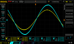
sine wave test up to clipping with 440nF+4,459R load
pic 1 22Vsupply 4,459Rload 20khz 860mVrms 440nFload 3k3 is not effecting - no oscillating with 2k7, 3k3,4k3
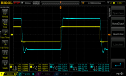
square wave with 4,459R + 440nF
pic 2 22Vsupply 4,459Rload 20khz 400mVrms square 440nF no resistor
pic 3 22Vsupply 4,459Rload 20khz 400mVrms square 440nF 3k3 at pin1_2
chris
last test before listening approach...
as FF wrote i did some checks of oscillating and i have to say this small bastard is stable !
sine wave test up to clipping with 440nF+4,459R load
pic 1 22Vsupply 4,459Rload 20khz 860mVrms 440nFload 3k3 is not effecting - no oscillating with 2k7, 3k3,4k3
square wave with 4,459R + 440nF
pic 2 22Vsupply 4,459Rload 20khz 400mVrms square 440nF no resistor
pic 3 22Vsupply 4,459Rload 20khz 400mVrms square 440nF 3k3 at pin1_2
chris
Attachments
UTC amp building
Hi
i soldered in the evening the 3k3 on both amp boards. gain is about 15.
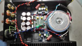
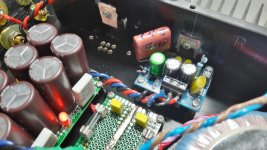
its a pre installation - nothing burned or is dead.....the case is the housing where i planned my parallel 1875 chip which failed.(power cable are too long and i mount the amp boards back to the transformer - not ideal.
I swapped the transformer from 18-0-18 to 15-0-15 (120VA) and get with both boards powered up a rail voltage on exactly 21,4V each. as you can see i have now different caps on the amp board but this comes from the failure searching and i keep it.
normally the amp boards have DC offset at 22V supply about minus 4-5mV. now i have -42,4mv and -52,3mV- this comes from the 3k3 resistor from pin1 - pin 2.
should i keep that DC offset?
input cable is needed and the connection of the speakers cable ---> then i let it run on the test lab...1-3- days .....after this i will start a sound session.
chris
Hi
i soldered in the evening the 3k3 on both amp boards. gain is about 15.
its a pre installation - nothing burned or is dead.....the case is the housing where i planned my parallel 1875 chip which failed.(power cable are too long and i mount the amp boards back to the transformer - not ideal.
I swapped the transformer from 18-0-18 to 15-0-15 (120VA) and get with both boards powered up a rail voltage on exactly 21,4V each. as you can see i have now different caps on the amp board but this comes from the failure searching and i keep it.
normally the amp boards have DC offset at 22V supply about minus 4-5mV. now i have -42,4mv and -52,3mV- this comes from the 3k3 resistor from pin1 - pin 2.
should i keep that DC offset?
input cable is needed and the connection of the speakers cable ---> then i let it run on the test lab...1-3- days .....after this i will start a sound session.
chris
Attachments
Hi
i soldered in the evening the 3k3 on both amp boards. gain is about 15.
its a pre installation - nothing burned or is dead.....the case is the housing where i planned my parallel 1875 chip which failed.(power cable are too long and i mount the amp boards back to the transformer - not ideal.
I swapped the transformer from 18-0-18 to 15-0-15 (120VA) and get with both boards powered up a rail voltage on exactly 21,4V each. as you can see i have now different caps on the amp board but this comes from the failure searching and i keep it.
normally the amp boards have DC offset at 22V supply about minus 4-5mV. now i have -42,4mv and -52,3mV- this comes from the 3k3 resistor from pin1 - pin 2.
should i keep that DC offset?
input cable is needed and the connection of the speakers cable ---> then i let it run on the test lab...1-3- days .....after this i will start a sound session.
chris
For a "final" amplifier I would trim out the 40-50mV offset, for a test amplifier I would do nothing. It will not change the sound and as soon as you change for instance the gain, also the offset will change.
Looking forward to hear your opinion about the sound.
For a "final" amplifier I would trim out the 40-50mV offset, for a test amplifier I would do nothing. It will not change the sound and as soon as you changes for instance the gain, also the offset will change.
Looking forward to hear your opinion about the sound.
Thanks FF...
i am tiered....Earth to chassis and the GND of the transformer (black) to chassis is ok?
sorry
- Home
- Amplifiers
- Chip Amps
- eBay mono LM1875 kit