I will check mine..........
Hi Chris,
I took three TDA2050 (brand new) and two LM1875 (fake but tested to be OK).
I used my DDM in 200 KOhm setting. I tried all combinations between pins 3, 4 and 5 and in all cases I had more than 200 KOhm.
Your DDM is set correctly to resistance and not for testing diode forward voltage? Resistance is not measured at 1KHz.
Hi FF
Thank you for your help. yes i have a DMM. i will check this again.
actually i am finished with a new board - but i have the same problem - i checked all components from the previous board ( were i had this failure) before soldering, i change the gain from 22k to 15 k + I used a new UTC2050. if i switched on I got the same behavior - voltage dropped.
i limited the current to 0,1 A at +/-22V supply and the lab supply goes into CC !!! if i switch on 1 supply it is stable!!!
i really do not understand .. i should stop and go into my listening room
chris
other boards are working
Thank you for your help. yes i have a DMM. i will check this again.
actually i am finished with a new board - but i have the same problem - i checked all components from the previous board ( were i had this failure) before soldering, i change the gain from 22k to 15 k + I used a new UTC2050. if i switched on I got the same behavior - voltage dropped.
i limited the current to 0,1 A at +/-22V supply and the lab supply goes into CC !!! if i switch on 1 supply it is stable!!!
i really do not understand
.. i should stop and go into my listening roomchris
other boards are working
Hi Chris,
If you tell me which circuit you use we can find the problem.
In general, when you have build a class AB and want to test it for the first time,
- test it for a start without load (a load allows high currents harming the amplifier),
- test it for a start with a moderate supply voltage until you are sure that it works,
- try first with shorted input and look for instability and excessive DC at the output.
From what you tell, I find DC offset at the output or oscillation likely problems. Defects in the TDA2050 seem to me less likely.
Hi Chris,
If you tell me which circuit you use we can find the problem.
In general, when you have build a class AB and want to test it for the first time,
- test it for a start without load (a load allows high currents harming the amplifier),
- test it for a start with a moderate supply voltage until you are sure that it works,
- try first with shorted input and look for instability and excessive DC at the output.
From what you tell, I find DC offset at the output or oscillation likely problems. Defects in the TDA2050 seem to me less likely.
Hi FF
Thank you for your help. i act like you advice me in the other thread:
first without load moderate supply - then go up with the supply voltage - current limited !!!
then easy load 8R or higher....etc.
but i cannot start to measure because my lab current limit kicks in!
+/-22V 0,1A CC each rail.
i use the mono pcb as known here. i checked all components with my LCR meter before i solder this in a new pcb mono board. its a really strange behavior to sort out what happened here... i beep araound the complete points but found nothing...
at the previous board i de solder all decoupling caps because i was thinking that the are faulty. then i check the board without chip and all components (+caps) - soldered in. then i get a functional board ....without chip
no current limiter kick in..so my interpretation was a faulty UTC2050...so actually i need to build a test board and check that the chip i want to implement into my mono board is ok. but as you wrote its unlikly that the chips are faulty..
is it possible that a cap is ok if i check it with LCR and if i power it up it getting weak ???
the reason i am asking is if i switch on one supply everything is fine - it does not matter if +22V or -22V at my lab supply its working. but if i switch the second additionally then the lab supply goes into the current limiter - in my case 0,1A and the voltage drops and toggle around about 2- 8..9Vmy target was to start with a compare test LM1875 vs UTC2050 mono board with the same supply and transformer (120VA) and same components.
i changed the transformer to a 120VA 15-0-15VAC and test my supply. so this step is ready
. i got unloaded about +/- 21VDC.so i need time to sort my thinking and recheck again again again...
chris
PeakTech 2170 is a really nice instrument but you may not be sure what the instrument believes it is looking at when you measure between pins of an IC. Do you have a traditional DDM (with manual measurement range setting) as well?
Yes i have 2 DMM Voltcraft but they are showing some 10M ohms always. dont ask my why
i use my LCR Meter at the DCR mode. this needs about 3 seconds to get a measurements. 1 UTC has other values - look at the attachment
chris
Attachments
Yes i have 2 DMM Voltcraft but they are showing some 10M ohms always. dont ask my why
i use my LCR Meter at the DCR mode. this needs about 3 seconds to get a measurements. 1 UTC has other values - look at the attachment
chris
Hi Chris,
"Always showing 10 MOhm": Also when you short-circuit the two test-pins?
The problem with your sophisticated LCR tester is that it expects a coil, a capacitor or a resistor at the input. You give it two contacts to an integrated circuit which is none of that. What will the meter the do? Automatically try to come to a value of an L, a C or an R without you knowing how.
When I measure with my DMM (not DDM of course), I know the DMM will show less than 1K if there is a problem. It is not that my DMM measures the impedance precisely, it is an empiric test that I have good experience with works in case of internal short-circuits.
Let's see if both your DMM are defect?
Last edited:
No FF- at the peaktech 2170 you can leave the automatic mode. if you switch manually to a mode e.g. DCR its measuring the DC resistance between 200 - 200M ohm.
actually i measured all UTC 24 are like all others 3 are different - 1 of them is complete out of range...as posted before.
chris
actually i measured all UTC 24 are like all others 3 are different - 1 of them is complete out of range...as posted before.
chris
No FF- at the peaktech 2170 you can leave the automatic mode. if you switch manually to a mode e.g. DCR its measuring the DC resistance between 200 - 200M ohm.
actually i measured all UTC 24 are like all others 3 are different - 1 of them is complete out of range...as posted before.
chris
From your scheme I see nothing alarming. I guess all your UTC2050 will work.
Are none of your DMM working?
From your scheme I see nothing alarming. I guess all your UTC2050 will work.
Are none of your DMM working?
Hi FF- strange but no the beep is working but if i want to measure this chips i get from pin 3 -4(5) 10M and between Pin 3 - 2(1) 30M. maybe the voltage at this setting is too small i dont know.
but yesterday night i was successfully install a new chip! i but out all caps and its partly working !- partly? yes no current limiting but i got - 21.6V at the output so i have to check the solder dots for the feedback and other dots. it was too late for me...
strange but no the beep is working but if i want to measure this chips i get from pin 3 -4(5) 10M and between Pin 3 - 2(1) 30M. maybe the voltage at this setting is too small i dont know.
You may need your DMMs in the future so see what is wrong with them. The "beep" is only for low impedance values.
10M and 30M corresponds to my indication of "high". No problem with the TDA2050.
but yesterday night i was successfully install a new chip! i but out all caps and its partly working !- partly? yes no current limiting but i got - 21.6V at the output so i have to check the solder dots for the feedback and other dots. it was too late for me...
Is it still only "partly working"? You probably have some 10 components in that circuit so we can do better than "partly".
Are you working at present or home due to corona-measures closing work-places?
Hi FF
DMM is not working for me...i do dont know what happened with my Voltcraft DMM in "R-Mode".
yes i am working at home(all schools are closed since a week) and my wife and my 2 kids too.
partly ? yes..... because of de soldering the solder dots- in this case at pin 4 was not connected to the RF + CF trace! so the amp goes to the neg rail.... -this is fixed now....but the 100pF CF has to be omitted because this was the reason why the amp is going strange = power supply goes to the current limiter?
i de-soldered 1 leg of the cap and the amp supply stays stable - as i but the leg back again to the pin 4 (OUT) the supply collapsed!!- current limiter was set at 0,1A. if i put the leg away the PSU immediately stay stable at 22V.
..strange for me because the cap is fine if i measure it with my LCR - 101pF
this cap:
CD15FD101JO3F | Glimmerkondensator, 100pF 500Vdc, Raster 5,9mm +125degC | RS Components
now the amp is working well with 8R and 4R as you see in the following post- without feedback cap of 100pF as the LM1875 liked.
chris
DMM is not working for me...i do dont know what happened with my Voltcraft DMM in "R-Mode".
yes i am working at home(all schools are closed since a week) and my wife and my 2 kids too.
partly ? yes..... because of de soldering the solder dots- in this case at pin 4 was not connected to the RF + CF trace! so the amp goes to the neg rail.... -this is fixed now....but the 100pF CF has to be omitted because this was the reason why the amp is going strange = power supply goes to the current limiter?
i de-soldered 1 leg of the cap and the amp supply stays stable - as i but the leg back again to the pin 4 (OUT) the supply collapsed!!- current limiter was set at 0,1A. if i put the leg away the PSU immediately stay stable at 22V.
..strange for me because the cap is fine if i measure it with my LCR - 101pFthis cap:
CD15FD101JO3F | Glimmerkondensator, 100pF 500Vdc, Raster 5,9mm +125degC | RS Components
now the amp is working well with 8R and 4R as you see in the following post- without feedback cap of 100pF as the LM1875 liked.
chris
mono board with UTC2050 without feedback cap
Hi
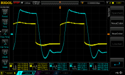
here are the results:
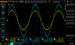
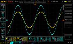
power supply Rigol DP820 +/-22V: 8R2 load
pic 1 22Vsupply no load 1khz 900mVrms in
pic 2 22Vsupply 8R2load 1khz 840mVrms in about 22Watt
pic 3 22Vsupply 8R2load 10khz 840mVrms
pic 4 22Vsupply 8R2load 80khz 600mVrms about 10W
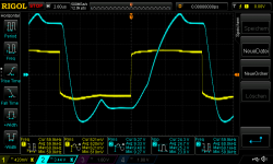
pic 5 22Vsupply 8R2load 20khz square 600mVrms
pic 6 22Vsupply 8R2load 50khz square 600mVrms
pic 7 22Vsupply 8R2load 80khz square 600mVrms
Hi
here are the results:
power supply Rigol DP820 +/-22V: 8R2 load
pic 1 22Vsupply no load 1khz 900mVrms in
pic 2 22Vsupply 8R2load 1khz 840mVrms in about 22Watt
pic 3 22Vsupply 8R2load 10khz 840mVrms
pic 4 22Vsupply 8R2load 80khz 600mVrms about 10W
pic 5 22Vsupply 8R2load 20khz square 600mVrms
pic 6 22Vsupply 8R2load 50khz square 600mVrms
pic 7 22Vsupply 8R2load 80khz square 600mVrms
Attachments
-
 22Vsupply 8R2load 80khz square 600mVrms.png47 KB · Views: 33
 -
 22Vsupply 8R2load 50khz square 600mVrms.png43 KB · Views: 35
 -
 22Vsupply 8R2load 20khz square 600mVrms.png43.1 KB · Views: 161
 -
 22Vsupply 8R2load 80khz 600mVrms about 10W.png49.1 KB · Views: 154
 -
 22Vsupply 8R2load 10khz 840mVrms.png49.9 KB · Views: 155
 -
 22Vsupply 8R2load 1khz 840mVrms in about 22Watt.png47.6 KB · Views: 156
 -
 22Vsupply no load 1khz 900mVrms in.png47.4 KB · Views: 161
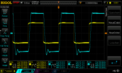
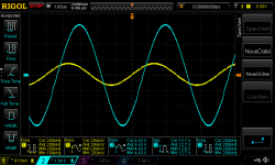
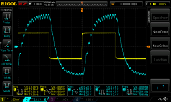
mono board with 4,459R and no feedback cap
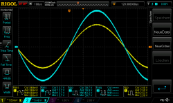
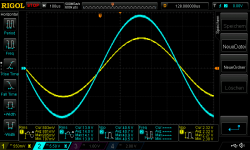
now the important measurements because of the better current capability of the utc chip (22V supply, max 25V!)
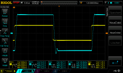
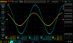
pic 1 22Vsupply 4,459Rload 1khz 840mVrms about 36,7Watt
pic 2 22Vsupply 4,459Rload 10khz 840mVrms
pic 3 22Vsupply 4,459Rload 80khz 600mVrms
pic 4 22Vsupply 4,459Rload 200khz 300mVrms
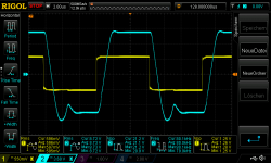
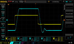
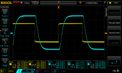
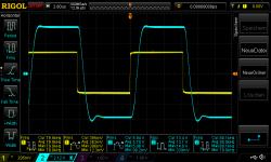
pic 5 22Vsupply 4,459Rload square 20khz 600mVrms
pic 6 22Vsupply 4,459Rload square 50khz 600mVrms
pic 7 22Vsupply 4,459Rload square 80khz 600mVrms first 2 seconds stable
pic 8 22Vsupply 4,459Rload square 80khz 600mVrms not stable after 4 seconds
pic 9 22Vsupply 4,459Rload square 60khz 600mVrms
target was to set the gain a little bit down --> Gain is about 15. feedback resistor is changed to 14k814.
i have to try out which feedback cap is working for the UTC at this configuration
chris
now the important measurements because of the better current capability of the utc chip (22V supply, max 25V!)
pic 1 22Vsupply 4,459Rload 1khz 840mVrms about 36,7Watt
pic 2 22Vsupply 4,459Rload 10khz 840mVrms
pic 3 22Vsupply 4,459Rload 80khz 600mVrms
pic 4 22Vsupply 4,459Rload 200khz 300mVrms
pic 5 22Vsupply 4,459Rload square 20khz 600mVrms
pic 6 22Vsupply 4,459Rload square 50khz 600mVrms
pic 7 22Vsupply 4,459Rload square 80khz 600mVrms first 2 seconds stable
pic 8 22Vsupply 4,459Rload square 80khz 600mVrms not stable after 4 seconds
pic 9 22Vsupply 4,459Rload square 60khz 600mVrms
target was to set the gain a little bit down --> Gain is about 15. feedback resistor is changed to 14k814.
i have to try out which feedback cap is working for the UTC at this configuration
chris
Attachments
-
 22Vsupply 4,459Rload square 80khz 600mVrms_2 not stable.png51.5 KB · Views: 31
 -
 22Vsupply 4,459Rload square 80khz 600mVrms_1.png50.3 KB · Views: 30
 -
 22Vsupply 4,459Rload square 50khz 600mVrms.png48.3 KB · Views: 30
 -
 22Vsupply 4,459Rload square 20khz 600mVrms.png47.9 KB · Views: 36
 -
 22Vsupply 4,459Rload 200khz 300mVrms.png47.8 KB · Views: 27
 -
 22Vsupply 4,459Rload 80khz 600mVrms.png48.5 KB · Views: 26
 -
 22Vsupply 4,459Rload 10khz 840mVrms.png49.5 KB · Views: 34
 -
 22Vsupply 4,459Rload 1khz 840mVrms about 36,7Watt.png50.9 KB · Views: 42
 -
 22Vsupply 4,459Rload square 60khz 600mVrms.png48.9 KB · Views: 32
Hi Chris,
Congratulations that you sorted out the initial "DIY" troubles!.
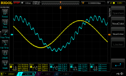
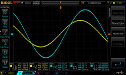
First thing i noticed is that i don't see your "familiar" oscillations on the sinus peaks…
It actually looks quite good and well... 37W at 4.5 ohm.. wow!
I am especially looking forward to your (future) listening and comparison tests on the UTC chip!
For sure your ears (and listening experience) are way beyond my capabilities in this respect.
In stead of paralleling and/or bridging Amp techniques i suggest to also consider bi-ampling techniques using these little boards.
For instance one PCB for the low and a second PCB for the mid/treble speaker.
If your speaker already is prepared for bi-amp connection it is an easy alternative to obtain "double" power per channel as well.
And it might very well have a greater impact on the aural perception.
Or use an active or passive crossover.
This little PCB is perfect for this application!
Congratulations that you sorted out the initial "DIY" troubles!.
First thing i noticed is that i don't see your "familiar" oscillations on the sinus peaks…
It actually looks quite good and well... 37W at 4.5 ohm.. wow!
I am especially looking forward to your (future) listening and comparison tests on the UTC chip!
For sure your ears (and listening experience) are way beyond my capabilities in this respect.
In stead of paralleling and/or bridging Amp techniques i suggest to also consider bi-ampling techniques using these little boards.
For instance one PCB for the low and a second PCB for the mid/treble speaker.
If your speaker already is prepared for bi-amp connection it is an easy alternative to obtain "double" power per channel as well.
And it might very well have a greater impact on the aural perception.
Or use an active or passive crossover.
This little PCB is perfect for this application!
Hi FF
DMM is not working for me...i do dont know what happened with my Voltcraft DMM in "R-Mode".
yes i am working at home(all schools are closed since a week) and my wife and my 2 kids too.
partly ? yes..... because of de soldering the solder dots- in this case at pin 4 was not connected to the RF + CF trace! so the amp goes to the neg rail.... -this is fixed now....but the 100pF CF has to be omitted because this was the reason why the amp is going strange = power supply goes to the current limiter?
i de-soldered 1 leg of the cap and the amp supply stays stable - as i but the leg back again to the pin 4 (OUT) the supply collapsed!!- current limiter was set at 0,1A. if i put the leg away the PSU immediately stay stable at 22V.
this cap:
CD15FD101JO3F | Glimmerkondensator, 100pF 500Vdc, Raster 5,9mm +125degC | RS Components
now the amp is working well with 8R and 4R as you see in the following post- without feedback cap of 100pF as the LM1875 liked.
chris
Hi Chris,
Well done !

From my experience, the 100pF does in some cases improve step response in other cases make the loop oscillate. When you have oscillation, the current consumption increases much.
So, next time you have made a class AB amplifier circuit, first test is without a load, input shorted and oscilloscope at the output. DC levels OK and no oscillation at the output with this simple configuration? If yes -> continue.
Hi Chris,
Well done !
From my experience, the 100pF does in some cases improve step response in other cases make the loop oscillate. When you have oscillation, the current consumption increases much.
So, next time you have made a class AB amplifier circuit, first test is without a load, input shorted and oscilloscope at the output. DC levels OK and no oscillation at the output with this simple configuration? If yes -> continue.
Hi FF
thanks for your kind words.
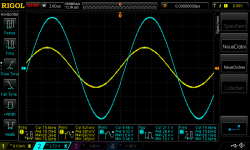
 i never ever expect that this 100pF makes this troubles!! to be honest i need a week to dont get very f... angry....
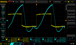
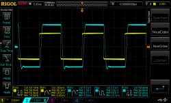
look here i did a test with different Cf caps..
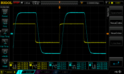
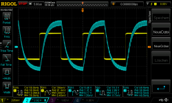
pic 1 22V supply 4,459R load 400mVrms in square wave 50khz_without Cf
pic 2 22V supply 4,459R load 400mVrms in square wave 50khz_with 100pF
pic 3 22V supply 4,459R load 400mVrms in sine wave 100khz_without Cf
pic 4 22V supply 4,459R load 400mVrms in sine wave 100khz_with 100pF
finally the 10pF 22pF, 47pF ceramic for testing -directly at the pin 2-4
pic 5 22V supply 4,459R load 400mVrms in square wave 80khz_without Cf
pic 6 22V supply 4,459R load 400mVrms in square wave 80khz_with 10pF
pic 7 22V supply 4,459R load 400mVrms in square wave 80khz_with 22pF
pic 8 22V supply 4,459R load 400mVrms in square wave 80khz_with 47pF
10pf or nothing?
chris
Attachments
-
 22V supply 4,459R load 400mVrms in square wave 80khz_with 22pF.png46.8 KB · Views: 31
 -
 22V supply 4,459R load 400mVrms in square wave 80khz_with 10pF.png45.2 KB · Views: 33
 -
 22V supply 4,459R load 400mVrms in square wave 80khz_without Cf.png46.9 KB · Views: 35
 -
 22V supply 4,459R load 400mVrms in sine wave 100khz_with 100pF.png47.9 KB · Views: 37
 -
 22V supply 4,459R load 400mVrms in sine wave 100khz_without Cf.png46.7 KB · Views: 41
 -
 22V supply 4,459R load 400mVrms in square wave 50khz_with 100pF.png57 KB · Views: 32
 -
 22V supply 4,459R load 400mVrms in square wave 50khz_without Cf.png46.5 KB · Views: 34
 -
 22V supply 4,459R load 400mVrms in square wave 80khz_with 47pF.png49.5 KB · Views: 27
................................
10pf or nothing?
chris
Nothing. Try a 1K resistor between the two input pins instead. 1K may not be the best value but see if it has an effect.
- Home
- Amplifiers
- Chip Amps
- eBay mono LM1875 kit