Hi Chris, how do you manage to invoke the OverCurrent Protection with a load of 8.2 Ohm? As far as I can see, you cannot get the peak current above 2.5A, most likely not even that much.
the chip goes into its self protection mode - maybe I wrote the wrong wording.
it is on some mili seconds then off - on - off- on - off - it looks like or lets say the chip reacts like a shorted at the output...
......
Very interesting to follow your findings, i have plenty of boards and parts still left and, am also considering to do a trial and test for the inverted config, using this board.
PS It still surprises me l how good this cheap little board actually sounds!
Fred
Hi Fred
Did you build an inverted version and compare sound wise with your amp?
chris
yes i have a cap at the input (green muse 10µF electrolytic). i did a check again..now and go 10mV more input the get a oscillation. output DC coupled....
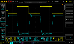
pic 1 inverted amp 22V supply 8,2R_square wave 1khz 890mVrms in oscillating
Hi
The feedback cap from the non inverting version is about 100pF to avoid oscillating . now in the inverted mod i get this output signal.
About my square wave output signal at the inverted mode it looks like a integrator opamp. its very "soft" integration:
Integrator / Integrierverstärker (Operationsverstärker)
according to this page the 90° swap from sinus to cos is not happened.
chris
Good morning Chris,
"according to this page the 90° swap from sinus to cos is not happened". The theory you cite is German and that is no longer applicable for constructions made in English (as used on this forum) after the Brexit - no more common rules!

Sorry, I adore silly jokes.
Your 100pF used in the feedback of the LM1875 will only have an effect at very high frequencies. At audio frequencies, the feedback resistor determines the transfer function and there you have no phase-turn. Even increasing the input frequency will hardly let you see the 90 degree phase-turn because the LM1875 slew-rate will put a limit before that.
The OP-AMP used in the composite amplifier version runs as a real integrator (no feedback resistor) and you have the 90 degree phase-turn.
Good morning Chris,
"according to this page the 90° swap from sinus to cos is not happened". The theory you cite is German and that is no longer applicable for constructions made in English (as used on this forum) after the Brexit - no more common rules!
Sorry, I adore silly jokes.
Your 100pF used in the feedback of the LM1875 will only have an effect at very high frequencies. At audio frequencies, the feedback resistor determines the transfer function and there you have no phase-turn. Even increasing the input frequency will hardly let you see the 90 degree phase-turn because the LM1875 slew-rate will put a limit before that.
The OP-AMP used in the composite amplifier version runs as a real integrator (no feedback resistor) and you have the 90 degree phase-turn.

Thanks FF
sqaure wave 4,459R + caps
Hi
i´d play around to find out which gain (10 or 6) is more stable with 4,4,59R + 440nF load:
Gain 10:
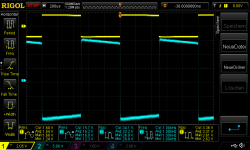
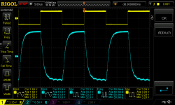
first pics without cap load - 4,459R load square wave input 1,7Vrms - about 50 Watt!!!-- fan is recommended
pic 1 inverted amp Gain 10 22V supply 4,459Rload_1,7Vrms in 1khz
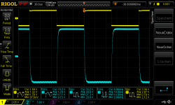
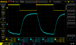
pic 2 inverted amp Gain 10 22V supply 4,459Rload_1,7Vrms in 10khz
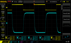
pic 3 inverted amp Gain 10 22V supply 4,459Rload_1,7Vrms in 20khz
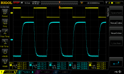
pic 4 inverted amp Gain 10 22V supply 4,459Rload_1,7Vrms in 30khz
pic 5 inverted amp Gain 10 22V supply 4,459Rload_1,7Vrms in 50khz
pic 6 inverted amp Gain 10 22V supply 4,459Rload_1,7Vrms in 70khz
chris
Hi
i´d play around to find out which gain (10 or 6) is more stable with 4,4,59R + 440nF load:
Gain 10:
first pics without cap load - 4,459R load square wave input 1,7Vrms - about 50 Watt!!!-- fan is recommended
pic 1 inverted amp Gain 10 22V supply 4,459Rload_1,7Vrms in 1khz
pic 2 inverted amp Gain 10 22V supply 4,459Rload_1,7Vrms in 10khz
pic 3 inverted amp Gain 10 22V supply 4,459Rload_1,7Vrms in 20khz
pic 4 inverted amp Gain 10 22V supply 4,459Rload_1,7Vrms in 30khz
pic 5 inverted amp Gain 10 22V supply 4,459Rload_1,7Vrms in 50khz
pic 6 inverted amp Gain 10 22V supply 4,459Rload_1,7Vrms in 70khz
chris
Attachments
-
 inverted amp Gain 10 22V supply 4,459Rload_1,7Vrms in 1khz.png47.4 KB · Views: 167
 -
 inverted amp Gain 10 22V supply 4,459Rload_1,7Vrms in 10khz.png47.8 KB · Views: 163
 -
 inverted amp Gain 10 22V supply 4,459Rload_1,7Vrms in 20khz.png46.5 KB · Views: 165
 -
 inverted amp Gain 10 22V supply 4,459Rload_1,7Vrms in 30khz.png50.4 KB · Views: 172
 -
 inverted amp Gain 10 22V supply 4,459Rload_1,7Vrms in 50khz.png46.5 KB · Views: 162
 -
 inverted amp Gain 10 22V supply 4,459Rload_1,7Vrms in 70khz.png45.6 KB · Views: 30
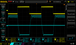
now Gain 10: with 4,459R + 440nF mkt caps
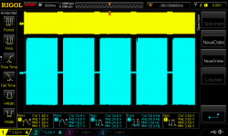
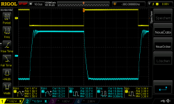
pic 1 inverted amp Gain 10 22V supply 4,459Rload_440nF cap_1,7Vrms in 1khz
pic 2 inverted amp Gain 10 22V supply 4,459Rload_440nF cap_1,7Vrms in 10khz
pic 3 inverted amp Gain 10 22V supply 4,459Rload_440nF cap_1,7Vrms in 20khz
the chip goes to its internal thermal ore current limiter
pic 4 inverted amp Gain 10 22V supply 4,459Rload_440nF cap_1,7Vrms in 20khz current limiter
chris
pic 1 inverted amp Gain 10 22V supply 4,459Rload_440nF cap_1,7Vrms in 1khz
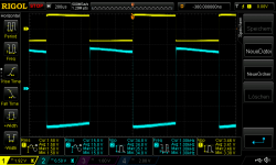
pic 2 inverted amp Gain 10 22V supply 4,459Rload_440nF cap_1,7Vrms in 10khz
pic 3 inverted amp Gain 10 22V supply 4,459Rload_440nF cap_1,7Vrms in 20khz
the chip goes to its internal thermal ore current limiter
pic 4 inverted amp Gain 10 22V supply 4,459Rload_440nF cap_1,7Vrms in 20khz current limiter
chris
Attachments
-
 inverted amp Gain 10 22V supply 4,459Rload_440nF cap_1,7Vrms in 20khz current limiter.png45.9 KB · Views: 36
 -
 inverted amp Gain 10 22V supply 4,459Rload_440nF cap_1,7Vrms in 20khz.png47.7 KB · Views: 32
 -
 inverted amp Gain 10 22V supply 4,459Rload_440nF cap_1,7Vrms in 10khz.png45.4 KB · Views: 32
 -
 inverted amp Gain 10 22V supply 4,459Rload_440nF cap_1,7Vrms in 1khz.png47.2 KB · Views: 33
last the Gain 6 + 4,459R + 440nF:
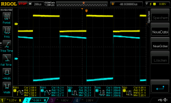
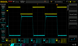
pic 1 inverted amp Gain 6 22V supply 4,459Rload_440nFcap_2,7Vrms in 1khz
pic 2 inverted amp Gain 6 22V supply 4,459Rload_440nFcap_2,7Vrms in 10khz
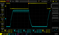
pic 3 inverted amp Gain 6 22V supply 4,459Rload_440nFcap_2,7Vrms in 20khz start oscillating- you really can see at the positive rail the the chip start to oscillating during 3-4 seconds
pic 4 inverted amp Gain 6 22V supply 4,459Rload_440nFcap_2,7Vrms in 20khz start oscillating + current limiter
so for me the Gain 6 (8k1 parallel to the 22kR) is little bit more stable but not really much.
chri
pic 1 inverted amp Gain 6 22V supply 4,459Rload_440nFcap_2,7Vrms in 1khz
pic 2 inverted amp Gain 6 22V supply 4,459Rload_440nFcap_2,7Vrms in 10khz
pic 3 inverted amp Gain 6 22V supply 4,459Rload_440nFcap_2,7Vrms in 20khz start oscillating- you really can see at the positive rail the the chip start to oscillating during 3-4 seconds
pic 4 inverted amp Gain 6 22V supply 4,459Rload_440nFcap_2,7Vrms in 20khz start oscillating + current limiter
so for me the Gain 6 (8k1 parallel to the 22kR) is little bit more stable but not really much.
chri
Attachments
-
 inverted amp Gain 6 22V supply 4,459Rload_440nFcap_2,7Vrms in 1khz.png48 KB · Views: 41
 -
 inverted amp Gain 6 22V supply 4,459Rload_440nFcap_2,7Vrms in 10khz.png48.6 KB · Views: 34
 -
 inverted amp Gain 6 22V supply 4,459Rload_440nFcap_2,7Vrms in 20khz start oscillating.png48.3 KB · Views: 45
 -
 inverted amp Gain 6 22V supply 4,459Rload_440nFcap_2,7Vrms in 20khz start oscillating + current .png53.2 KB · Views: 44
If you start using fast OP amps in front of the chip amp, be careful.
If a very fast signal is at the input, the slew rate of the OP-amp has to be matched by the next stage for it´s gain. This is impossible at some point, as no power amp can follow this multiplication.
This is a strong argument to use an input filter!
@Chris I see all kinds of power supply influence, over temperature and maybe over current limiter´s in your pictures.
If you have one thing under control, you will drive the next factor into limitation.
This has no practical value any more.
Please do not get me wrong, but this will not lead to sonic improvement. You do not find any advantages from this over driving.
If the aim was to build an amp (I still see it as an educational experiment!), you would now build some prototypes and measure them, but only with reasonable test´s!
Just because your advanced equipment can produce such tests, the real amp does not have to deal with them.
Like your SUV can be driven on a Formula 1 race track, but will tilt over if you try to reach F1 cornering speed.
There are limit´s with any amp in this world. You only need a load resistor large enough and an input signal high enough and you can find points where the amp gives up.
Like driven into clipping at 20.000 Hz. This is something that never ever happens with music! If it does, the tweeter burns, the amp does not care.
If it was an idiot proof commercial product, you would find a limiter in the input that would prevent any of your extreme tests and the same at the output. So the amp never
sees your input and never goes unstable.
This is what you see in some pictures, where the amp simply cut´s out.
So, please, stay realistic, take into account Ohm´s law and don´t fall into the old trap: "Wer viel misst, misst viel Mist".
Maybe some idea to follow:
From a practical point of view, today I would use a dual SMPS to power such an amp. The commercial high end products show that even A/B amps are better off with such a power supply, as it does keep it´s voltage constant, if done right. Any stage of the power amp has stable voltages and this should improve the last edge of sonic performance.
Sure, any one from old school DIYS will feel more comfortable with a simple transformer, rectifier and caps, as we can understand it on first sight.
I would concentrate on improving the SMPS in connection with the amp, until it measures identical or better than the conventional PS.
Then do extensive listening tests, A-B.
Never forget, an amp is made to satisfy your ears, not your RIGOL.
Hi Turbowatch 2
yes you are right, my findings are maybe not helpful for audio purpose but i am still in my learning phase - i try out what i am want to see -- if a chip is dead - i don´t care ----> i have enough LM1875 chips and 30pcs of UTC2050.
these are not "quality sound" tests and for sure for listening this kind of power is not needed at home - i know.
any ideas to approve that chip from your side? gain setting - inverted mode...etc...what you tried?......any experience?
chris
Chris, the LM1875 is nice to play around, learn basics around amps, try the scope etc.
To improve it´s sound quality, there is one single step to make: Get yourself a few LM3886. If you start with a single chip, you will have something better than the best you can get out of a bucket full of LM1875.
If you take 12 of the LM3886, you can compose a world class stereo amp.
That is all.
If you want to gain some additional experience, try the LM1875 with two SMPS or a single dual voltage. A real one, not your lab supply. This should give you the best sound you can get with minimum cost and without the weight of a transformer.
The SMPS principle has too many advantages to ignore, they are the future of HIFI. Please realize that there are many car amps of highest quality. Many tests, top car amp versus High End home amp, have given very disturbing results. All these car amps have switch mode supplies. There is not that much difference from transforming 340 volt DC down or 12 volt DC up. Just a matter of Ampere...
If you want cheap, well made LM3886 for a start, look for this one, it has anything the data sheet asks for:
HiFi LM3886TF Mono 68W 4Ω Audio-LeistungsverstaRkerplatine AMP 50W / 38W 8Ω G9Z4 | eBay
or, stereo
Assembled 68w+68w HIFI lm3886tf Stereo Amplifier AMP Board 50w*2/38w*2 v9t6 | eBay
Last edited:
Thanks turbowatch2
your statement is clear that you propose to use a LM3886 for 1 chip solution.(I ordered your proposal from 1 month ago lm3886 XY pcb....need a month for delivery)
SMPS...you are right....as i posted in some threads i start with Class D , FX502pro and TPA3255 (what is wrong..) and i was surprised by the quality of my meanwell supply's.
chris
Last edited:
I would use the LM3886 as a 2x3 bridged amp. That should drive almost any speaker on the planet. Such an amp can deliver around 30A of current. The output power depends on the PS voltage, but up to 200W into 8 Ohms and 400W /4 Ohms at 0.1 THD should do it.
You only need 35V for this power, bridged. The only downside is a huge heat sink, to use this power continuously. Always remember, any parameter of a semi conductor is temperature dependent! So even if you do not use the power, keeping it on a constant temperature will help the sound.
For me that would be the last A/B amp to build.
At idle such a 6x chip amp would draw 21W, This is quite some serious heat.
Maybe use a nice D-amp in summer and keep yourself warm in winter with an LM3886 monster?
Last edited:
I would use the LM3886 as a 2x3 bridged amp. That should drive almost any speaker on the planet. Such an amp can deliver around 30A of current. The output power depends on the PS voltage, but up to 200W into 8 Ohms and 400W /4 Ohms at 0.1 THD should do it.
You only need 35V for this power, bridged. The only downside is a huge heat sink, to use this power continuously. Always remember, any parameter of a semi conductor is temperature dependent! So even if you do not use the power, keeping it on a constant temperature will help the sound.
For me that would be the last A/B amp to build.
At idle such a 6x chip amp would draw 21W, This is quite some serious heat.
Maybe use a nice D-amp in summer and keep yourself warm in winter with an LM3886 monster?
yes yes...do it

i am happy with some "clean" watts in my small room. ...but if i need really more power my brohter has a hifi akademie class D amp with 4x250W -and open baffle like mister Reith (constructor) has it
35V rail --> bridged and 200W into 8R? - peak?
Last edited:
Hi everyone, back to the Ebay Mono boards, if you guys don't mind
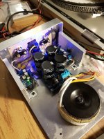
I finally played some music with my build last night (The enclosure is 'minimal' to say the least).
2xEbay Boards with the components Rabbitz suggested (all legit parts from Digikey). A 2x18v 100VA transformer and 20000uf per rail supply. Oddly enough the transfo gives me +- 27VDC once rectified (it seems wound for a bit over 18v). Now Im 6v under the 60V max supply for the chip, so I assume Im ok here.
The dc offset was 1.7 and 2.2mV, that's acceptable right?
Now I get a kinda annoying thump sound when I power up or down the amp, I remember reading that some experienced that with legit LM1875s, did anyone find a fix for that?
Aside from that well, I couldn't stop listening to it, I was so excited to have my first DIY amplifier working.
Thanks,
-Joey
Attachments
Last edited:
Hey Joey
Congratulation for your first DIY amp build !!! Fine that you keep reading and doing !
nice amp! you will enjoy hundreds of hours
DC offset is ok.
the thump is at power on and power of because the LM1875 has no mute pin- so therefore before switch on/off the amp disconnect 1 cable of your speakers each side and you get no thump in your speakers. actually i did step forward for a circuit for on/off pop.
chris
Last edited:
Thanks for the good words Chris.
I did find your comments about the pop off but if I understood correctly you didnt implement a solution yet?
I have a cheapo "speaker protection board" from ebay, which is really just 4 relays with a time delay. I might end up using this if I can find the space. Will test it out of the enclosure tonight.
Im keeping the amp away from my main speakers for now, for that reason.
- Home
- Amplifiers
- Chip Amps
- eBay mono LM1875 kit