Hi
If you increase PSU voltages, does that disappear?
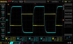
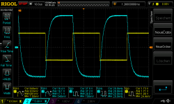
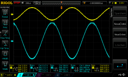
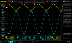
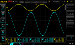
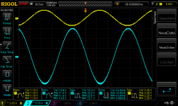
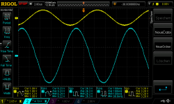
no it doesn't´t matter which voltage is set. if i set 22V and then 25V it don't get better.
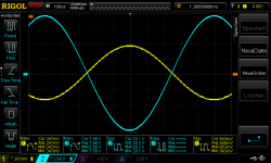
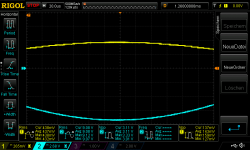
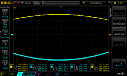
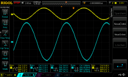
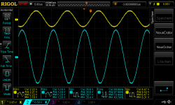
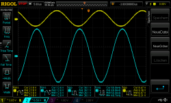
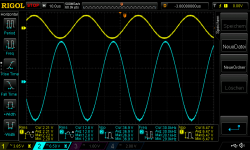
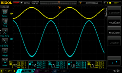
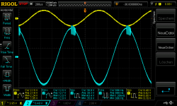
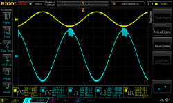
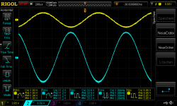
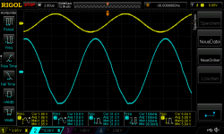
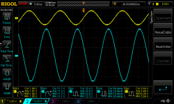
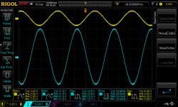
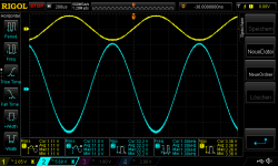
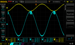
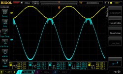
this behavior start at 350mV (at both supply voltages 22V or 25 the same)
pic 1inverted amp 22V supply 4,459R_350mVrms in oscillating start at negative rail_1
pic 2 inverted amp 22V supply 4,459R_350mVrms in oscillating start at negative rail_2
chris
If you increase PSU voltages, does that disappear?
no it doesn't´t matter which voltage is set. if i set 22V and then 25V it don't get better.
this behavior start at 350mV (at both supply voltages 22V or 25 the same)
pic 1inverted amp 22V supply 4,459R_350mVrms in oscillating start at negative rail_1
pic 2 inverted amp 22V supply 4,459R_350mVrms in oscillating start at negative rail_2
chris
Attachments
Does anyone know where I might be able to get a kicad or eagle file for the LM1875 mono board? I have the parts listed in this thread and they don't fit very well on the chinese board. Also, the boards I have are of pretty poor quality.
Ask the OP on this thread:
Yet another LM1875 amp - review request
Later layouts are near the end of the thread.
sqaure wave test into 8,2R load
Hi
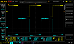
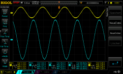
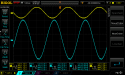
i testes my inverted board with square wave - +/- 22V supply -into 8,2R no caps at the load ...at the moment.
its not easy to see with sqare wave the "clipping" because the square goes a little bit down and at clipping you can see the its starts to get flat.
pic 1 inverted amp with square wave 22V supply 930mVrms in no load
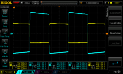
pic 2 inverted amp 22V supply 8,2R_square wave 1khz 830mVrms in about 39Watt
pic 3 inverted amp 22V supply 8,2R_square wave 10khz 910mVrms in about 39Watt
pic 4 inverted amp 22V supply 8,2R_square wave 20khz 900mVrms in about
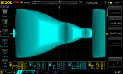
pic 5 is a sweep with 500mVrms sine wave from 10hz to 70khz in 5 seconds - i set my time scale "long" so you can see the frequency response.....strange look
i did the some measurements agian:
500mVrms in sine wave 8,2R load
10khz 11,1Vrms
20khz 9,88Vrms
30khz 8,91 Vrms
50khz 8,08vrms
70khz 7,02Vrms
chris
Hi
i testes my inverted board with square wave - +/- 22V supply -into 8,2R no caps at the load ...at the moment.
its not easy to see with sqare wave the "clipping" because the square goes a little bit down and at clipping you can see the its starts to get flat.
pic 1 inverted amp with square wave 22V supply 930mVrms in no load
pic 2 inverted amp 22V supply 8,2R_square wave 1khz 830mVrms in about 39Watt
pic 3 inverted amp 22V supply 8,2R_square wave 10khz 910mVrms in about 39Watt
pic 4 inverted amp 22V supply 8,2R_square wave 20khz 900mVrms in about
pic 5 is a sweep with 500mVrms sine wave from 10hz to 70khz in 5 seconds - i set my time scale "long" so you can see the frequency response.....strange look
i did the some measurements agian:
500mVrms in sine wave 8,2R load
10khz 11,1Vrms
20khz 9,88Vrms
30khz 8,91 Vrms
50khz 8,08vrms
70khz 7,02Vrms
chris
Attachments
-
 inverted amp with square wave 22V supply 930mVrms in no load.png44.6 KB · Views: 229
 -
 inverted amp 22V supply 8,2R_square wave 1khz 830mVrms in about 39Watt.png44.4 KB · Views: 220
 -
 inverted amp 22V supply 8,2R_square wave 10khz 910mVrms in about 39Watt.png45.7 KB · Views: 221
 -
 inverted amp 22V supply 8,2R_square wave 20khz 900mVrms in about.png46.6 KB · Views: 39
 -
 sweep with 10hz to 70khz 500mVrms in 8,2R.png67.9 KB · Views: 44
Last edited:
Hi
i testes my inverted board with square wave - +/- 22V supply -into 8,2R no caps at the load ...at the moment.
its not easy to see with sqare wave the "clipping" because the square goes a little bit down and at clipping you can see the its starts to get flat.
pic 1 inverted amp with square wave 22V supply 930mVrms in no load
pic 2 inverted amp 22V supply 8,2R_square wave 1khz 830mVrms in about 39Watt
pic 3 inverted amp 22V supply 8,2R_square wave 10khz 910mVrms in about 39Watt
pic 4 inverted amp 22V supply 8,2R_square wave 20khz 900mVrms in about
pic 5 is a sweep with 500mVrms sine wave from 10hz to 70khz in 5 seconds - i set my time scale "long" so you can see the frequency response.....strange look
i did the some measurements agian:
500mVrms in sine wave 8,2R load
10khz 11,1Vrms
20khz 9,88Vrms
30khz 8,91 Vrms
50khz 8,08vrms
70khz 7,02Vrms
chris
Hi Chris,
Since you have this falling slope on your first square-wave pictures, could it be because your scope is AC coupled?
You seem to have a -3dB bandwidth near 60KHz. As I recall, I had a bandwidth near 180KHz but with a much lower gain so that sounds consistent.
I guess you did the frequency-scan with a sine-wave at the input?
Last edited:
Hi Chris,
Since you have this falling slope on your first square-wave pictures, could it be because your scope is AC coupled?
You seem to have a -3dB bandwidth near 60KHz. As I recall, I had a bandwidth near 180KHz but with a much lower gain so that sounds consistent.
I guess you did the frequency-scan with a sine-wave at the input?
Since you have this falling slope on your first square-wave pictures, could it be because your scope is AC coupled?
yes
I guess you did the frequency-scan with a sine-wave at the input?
yes
") chris
chrisfor lower gain you use 7k5 and 2k2?
Since you have this falling slope on your first square-wave pictures, could it be because your scope is AC coupled?
yes
I guess you did the frequency-scan with a sine-wave at the input?
yes
for lower gain you use 7k5 and 2k2?
These are the values I use for -3.5 times gain.
Calling Vienna:
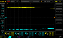
Chris, what you see as ripple at the negative supply rail is probably the switching frequency of the power supply.
Any regulated supply has some tiny voltages that dance over the DC.
Maybe put a very light load like 1k resistor and run your 25V or so output voltage over it. Connect the scope. So, only your supply, a resistor and the scope, to make it clear. No amp or such. Now you take the AC input of your scope and increase the resolution in steps.
First you only see the horizontal line of your regulated supply. The higher you go, the straight line becomes a little "fuzzy".
Usually some of these "sprites" dancing on the DC are periodic, others are irregular.
If, for example, a neon light with old fashion starter is switched on in your room, you will clearly see that. If you have an electric shaver, "BRAUN" preferred, switching it on and off will give a huge impact (sometimes you hear it in a playing radio or a flat screen TV will loose it´s picture for a second, maybe tone will cut out if connected to the same phase of your wall outlets).
If we look at DC it is usually like looking at a glas of water. It seems clear, but under the microscope shows all kind of organisms.
If you have a huge stock of capacitors, you could clean up this noise on the supply line with small valued ones. Depending on the caps construction and material, you can find combinations that address specific kinds of noise. Tantal, ceramic and very small film caps, like Styroflex will show different results. Here, the same capacity will not show the same results! This is why often different kinds of caps are used in parallel.
There is one point to consider: The limitations of a digital scope, as the old style analog kind is much faster, so maybe you don´t even see all of the stuff ghosting around.
Attachments
These are the values I use for -3.5 times gain.
Thanks..yesterday evening i start with my inverted amp and the resistors at home.
2k2 and 8k.
Thanks Turbowatch.
I tried the bench light turning up and down - no effect --- and yes its my regulated PSU = Rigol DP832. at this board ....what i was surprised is that the inverted loose bit gain but is more stable then the non inverted about oscillating and therefore you got more power out.
chris
I tried the bench light turning up and down - no effect --- and yes its my regulated PSU = Rigol DP832. at this board ....what i was surprised is that the inverted loose bit gain but is more stable then the non inverted about oscillating and therefore you got more power out.
chris
Since you have this falling slope on your first square-wave pictures, could it be because your scope is AC coupled?
yes
I guess you did the frequency-scan with a sine-wave at the input?
yes
for lower gain you use 7k5 and 2k2?
sorry i thought i did a failure but the scope at the output (blue line) was DC coupled
sorry i thought i did a failure but the scope at the output (blue line) was DC coupled
It is the decline of the horizontal blue parts that surprise me a bit. But, you have a signal coupling capacitor at the input?
It is the decline of the horizontal blue parts that surprise me a bit. But, you have a signal coupling capacitor at the input?
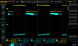
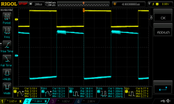
yes i have a cap at the input (green muse 10µF electrolytic). i did a check again..now and go 10mV more input the get a oscillation. output DC coupled
pic 1 inverted amp 22V supply 8,2R_square wave 1khz 890mVrms in oscillating
Attachments
mono kit with 6 Gain...and it worked !
Hi
i did it! i set my mono board (inverted) to gain about 6. i used a 8k (8191) parallel to the 22k feedback resistor and solder it there (under the pcb):
01,V more and you get oscliaating and additionally 0,1V more and you get clipping...fine
here are the results - the input is no in V not in mV: 22v supply 8,2R load
pic 1 inverted amp Gain 6 22V supply 8,2Rload_1,5Vrms in 1khz
pic 2 inverted amp Gain 6 22V supply 8,2Rload_2,4Vrms in 1khz oscillating
pic 3 inverted amp Gain 6 22V supply 8,2Rload_2,5Vrms in 1khz oscillating + clipping
pic 4 inverted amp Gain 6 22V supply 8,2Rload_3,3Vrms square in 1khz oscillating
Hi
i did it! i set my mono board (inverted) to gain about 6. i used a 8k (8191) parallel to the 22k feedback resistor and solder it there (under the pcb):
01,V more and you get oscliaating and additionally 0,1V more and you get clipping...fine
here are the results - the input is no in V not in mV
: 22v supply 8,2R loadpic 1 inverted amp Gain 6 22V supply 8,2Rload_1,5Vrms in 1khz
pic 2 inverted amp Gain 6 22V supply 8,2Rload_2,4Vrms in 1khz oscillating
pic 3 inverted amp Gain 6 22V supply 8,2Rload_2,5Vrms in 1khz oscillating + clipping
pic 4 inverted amp Gain 6 22V supply 8,2Rload_3,3Vrms square in 1khz oscillating
Attachments
-
 inverted amp Gain 6 22V supply 8,2Rload_1,5Vrms in 1khz.png45.5 KB · Views: 148
 -
 inverted amp Gain 6 22V supply 8,2Rload_2,4Vrms in 1khz oscillating.png46.9 KB · Views: 151
 -
 inverted amp Gain 6 22V supply 8,2Rload_2,5Vrms in 1khz oscillating + clipping.png47.5 KB · Views: 142
 -
 inverted amp Gain 6 22V supply 8,2Rload_3,3Vrms square in 1khz oscillating.png43.4 KB · Views: 148
part 2
frequency response: the gain is about 5,45 and get down to 4,8
pic 1 inverted amp Gain 6 22V supply 8,2Rload_2,3Vrms in 10khz
pic 2 inverted amp Gain 6 22V supply 8,2Rload_2,3Vrms in 20khz
pic 3 inverted amp Gain 6 22V supply 8,2Rload_2,3Vrms in 30khz
the negative rail starts to be "strange"
pic 4 inverted amp Gain 6 22V supply 8,2Rload_2,3Vrms in 50khz
pic 5 inverted amp Gain 6 22V supply 8,2Rload_2,3Vrms in 70khz
pic 6 inverted amp Gain 6 22V supply 8,2Rload_2,3Vrms in 100khz
pic 7 inverted amp Gain 6 22V supply 8,2Rload_2,3Vrms in 130khz
pic 8 inverted amp Gain 6 22V supply 8,2Rload_2,3Vrms in 130khz ocp on
the amp dont like that for more then some seconds
chris
Attachments
-
 inverted amp Gain 6 22V supply 8,2Rload_2,3Vrms in 130khz - ocp on.png49.8 KB · Views: 35
 -
 inverted amp Gain 6 22V supply 8,2Rload_2,3Vrms in 130khz.png51.1 KB · Views: 31
 -
 inverted amp Gain 6 22V supply 8,2Rload_2,3Vrms in 100khz.png49.6 KB · Views: 31
 -
 inverted amp Gain 6 22V supply 8,2Rload_2,3Vrms in 70khz.png53.4 KB · Views: 27
 -
 inverted amp Gain 6 22V supply 8,2Rload_2,3Vrms in 50khz.png50.3 KB · Views: 31
 -
 inverted amp Gain 6 22V supply 8,2Rload_2,3Vrms in 30khz.png52.4 KB · Views: 32
 -
 inverted amp Gain 6 22V supply 8,2Rload_2,3Vrms in 20khz.png53.8 KB · Views: 35
 -
 inverted amp Gain 6 22V supply 8,2Rload_2,3Vrms in 10khz.png47.8 KB · Views: 33
inverted amp Gain 6 and 4,459R load
here are the results with 4,459R at the amp 22v supply - its 1 mono board
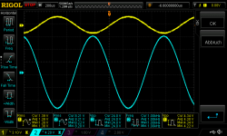
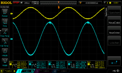
pic 1 inverted amp Gain 6 22V supply 4,459Rload_2,1Vrms in 1khz about 28Watt
pic 2 inverted amp Gain 6 22V supply 4,459Rload_2,2Vrms in 1khz about oscillating
more supply does not help - here 1 pic with 25Vsupply
pic 3 inverted amp Gain 6 25V supply 4,459Rload_2,3Vrms in 1khz about oscillating
chris
here are the results with 4,459R at the amp 22v supply - its 1 mono board
pic 1 inverted amp Gain 6 22V supply 4,459Rload_2,1Vrms in 1khz about 28Watt
pic 2 inverted amp Gain 6 22V supply 4,459Rload_2,2Vrms in 1khz about oscillating
more supply does not help - here 1 pic with 25Vsupply
pic 3 inverted amp Gain 6 25V supply 4,459Rload_2,3Vrms in 1khz about oscillating
chris
Attachments
Last edited:
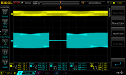
part 2 - frequency response - strange negative supply:
pic 1 inverted amp Gain 6 22V supply 4,459Rload_2,1Vrms in 10khz
pic 2 inverted amp Gain 6 22V supply 4,459Rload_2,1Vrms in 20khz
pic 3 inverted amp Gain 6 22V supply 4,459Rload_2,1Vrms in 30khz
pic 4 inverted amp Gain 6 22V supply 4,459Rload_2,1Vrms in 50khz
pic 5 inverted amp Gain 6 22V supply 4,459Rload_2,1Vrms in 70khz
pic 6 inverted amp Gain 6 22V supply 4,459Rload_2,1Vrms in 100khz +ocp after some seconds
with 100khz input the map goes after some seconds into ocp
Attachments
-
 inverted amp Gain 6 22V supply 4,459Rload_2,1Vrms in 100khz +ocp after some seconds.png49.6 KB · Views: 36
 -
 inverted amp Gain 6 22V supply 4,459Rload_2,1Vrms in 70khz.png54.5 KB · Views: 32
 -
 inverted amp Gain 6 22V supply 4,459Rload_2,1Vrms in 50khz.png51.1 KB · Views: 29
 -
 inverted amp Gain 6 22V supply 4,459Rload_2,1Vrms in 30khz.png53 KB · Views: 31
 -
 inverted amp Gain 6 22V supply 4,459Rload_2,1Vrms in 20khz.png53.7 KB · Views: 28
 -
 inverted amp Gain 6 22V supply 4,459Rload_2,1Vrms in 10khz.png47.9 KB · Views: 30
inverted mono kit with Gain of 10
Good evening
Gain= 10 (20db) is done by 18k parallel to 22k feedback resistor:
yes i should change the other 22k with a 18k resistor in parallel too....not done yet
supply +/-22V
pic 1 inverted amp Gain 10 22V supply 4,459Rload_1,2Vrms in 1khz about 27Watt
pic 2 inverted amp Gain 10 22V supply 4,459Rload_1,3Vrms in 1khz oscillating
pic 3 inverted amp Gain 10 22V supply 4,459Rload_1,4Vrms in 1khz oscillating + clipping
Attachments
part 2
frequency response: the gain is about 5,45 and get down to 4,8
pic 1 inverted amp Gain 6 22V supply 8,2Rload_2,3Vrms in 10khz
pic 2 inverted amp Gain 6 22V supply 8,2Rload_2,3Vrms in 20khz
pic 3 inverted amp Gain 6 22V supply 8,2Rload_2,3Vrms in 30khz
the negative rail starts to be "strange"
pic 4 inverted amp Gain 6 22V supply 8,2Rload_2,3Vrms in 50khz
pic 5 inverted amp Gain 6 22V supply 8,2Rload_2,3Vrms in 70khz
pic 6 inverted amp Gain 6 22V supply 8,2Rload_2,3Vrms in 100khz
pic 7 inverted amp Gain 6 22V supply 8,2Rload_2,3Vrms in 130khz
pic 8 inverted amp Gain 6 22V supply 8,2Rload_2,3Vrms in 130khz ocp on
the amp dont like that for more then some seconds
chris
Hi Chris, how do you manage to invoke the OverCurrent Protection with a load of 8.2 Ohm? As far as I can see, you cannot get the peak current above 2.5A, most likely not even that much.
Last edited:
part 2 gain 10
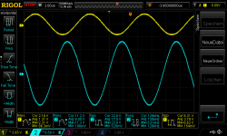
gain 10 (9,1 real), one mono board
frequency response:
pic 1 inverted amp Gain 10 22V supply 4,459Rload_1,2Vrms in 10khz about 26,6Watt
pic 2 inverted amp Gain 10 22V supply 4,459Rload_1,3Vrms in 20khz
pic 3 inverted amp Gain 10 22V supply 4,459Rload_1,3Vrms in 30khz
pic 4 inverted amp Gain 10 22V supply 4,459Rload_1,3Vrms in 50khz
pic 5 inverted amp Gain 10 22V supply 4,459Rload_1,3Vrms in 70khz
pic 6 inverted amp Gain 10 22V supply 4,459Rload_1,3Vrms in 100khz
gain of about 7 => about 17db
no ocp but if i switch the frequency to 110khz it immediately goes into the ocp
chris
Attachments
-
 inverted amp Gain 10 22V supply 4,459Rload_1,3Vrms in 70khz.png52.5 KB · Views: 30
 -
 inverted amp Gain 10 22V supply 4,459Rload_1,3Vrms in 50khz.png49.8 KB · Views: 28
 -
 inverted amp Gain 10 22V supply 4,459Rload_1,3Vrms in 30khz.png51.4 KB · Views: 28
 -
 inverted amp Gain 10 22V supply 4,459Rload_1,3Vrms in 20khz.png48.7 KB · Views: 32
 -
 inverted amp Gain 10 22V supply 4,459Rload_1,2Vrms in 10khz about 26,6Watt.png47.2 KB · Views: 32
 -
 inverted amp Gain 10 22V supply 4,459Rload_1,3Vrms in 100khz.png47.1 KB · Views: 35
- Home
- Amplifiers
- Chip Amps
- eBay mono LM1875 kit