.........page 8 and 9 in the tex. inst. data sheet........:
NOTE
When using a single supply, maximum transfer of heat away from the LM1875 can be
achieved by mounting the device directly to the heat sink (tab is at ground potential); this
avoids the use of a mica or other type insulator.
If I read that too fast I would've assumed the tab was linked to GND not V-- ... still weird IMHO that its only in the form of a note in the power dissipation section.
They also say "...or the heat sink can be isolated from the
chassis so the mica washer is not needed. This will change the required heat sink to..."
Still no mention of it being V--
Meh no big deal, I just find it midly annoying is all... I will do my testing with the heatsink off the chassis.
pin3 is -Vee and connected to the tab (metal backside of the chipamp).
either you use it
with a single supply (figure 2), so pin 3 is on ground and the heatsink too (same potential), you must not isolate it (but some people do it to avoid ground loops)........
or a ("split") dual supply,so the -Vee is on the tab and if the heatsink is on ground (not isolated against ground),you create a short between -Vee and ground,so you should isolate the backside of the chipamp .........
Better off using an insulator between the chip and heatsink otherwise you have to isolate the heatsink in the enclosure plus with live voltage on the heatsink is an accident waiting to happen when probing around. You still need thermal compound between the heatsink and the chip if you use this method.
Mica with thermal compound or silicon pads works well but don't forget the insulating bush for the mounting screw. When installed it is vital to check with a DMM the heatsink to the chip tab to ensure it's isolated (no conduction).
Other thing to note is I ground my heatsinks which can't be done without insulators.
Thanks everyone, I did understand it from the first comment by Chris :
"pin 3 (-V) is connected to the mounting plate of the LM1875"
That was clear enough, what wasn't clear IMHO is the datasheet. But that's no big deal, just annoying to have to wait on yet some other parts.
Thanks,
"pin 3 (-V) is connected to the mounting plate of the LM1875"
That was clear enough, what wasn't clear IMHO is the datasheet. But that's no big deal, just annoying to have to wait on yet some other parts.
Thanks,
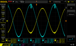
inverted mode with this kit - first try
Hi
i tried to get the mono board into an inverted amplifier and after some changes. i got it! first i tested the non inverted amp with 25 supply and 8,2R.
DC offset -1,9mV Gain about 22,14
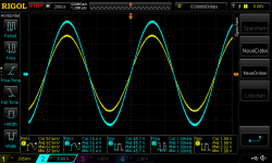
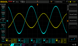
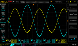
pic 1 non inverted amp 25V supply no load_700mVrms in
pic 2 non inverted amp 25V supply 8,2Rload_540mVrms in about 15,4Watt(don´t ask me why i changed the timescale ;-))
pic 3 non inverted amp 25V supply 8,2Rload_560mVrms in oscillating about 17,56Watt
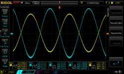
after some failed tests...I changed the layout and got the inverted amp:
i changed the pcb traces for the pin 1 and 2 and moved the Rfb and Cfb to the inverted pin2. so i get at the non inverted input the 1kR and the bipolar to GND.
i forgot to measure the DC offset...you see it on the cope pics- asymmetric!
gain about 20
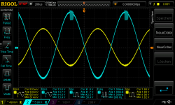
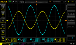
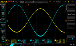
pic 4 inverted amp 25V supply no load_760mVrms in
pic 5 inverted amp 25V supply 8,2Rload_610mVrms in about 18,48Watt
pic 6 inverted amp 25V supply 8,2Rload_680mVrms in oscillating about 22,56Watt
more powerful but i realized too late a massive DC offset!! switch on i got about 0,7V but this goes up after testing with loa to 1,1V
to correct the DC voltage i have to change the bipolar cap at the non inverted pin to a polar cap?? correct ?
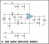
please look at the schematic (pic 7)and think about that the Rfb is from pin4 to the pin2 inverted pin.(parallel is a 100pF to get less oscillating- the same was at the non inverted amp)
pic 8 is the try that the bipolar cap is not ok -i did following:
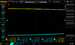
no power supply = dead amp--> input signal yellow -- output signal at the output terminal. i got a sine wave singal with DC offset about +92mV
chris
Hi
i tried to get the mono board into an inverted amplifier and after some changes. i got it! first i tested the non inverted amp with 25 supply and 8,2R.
DC offset -1,9mV Gain about 22,14
pic 1 non inverted amp 25V supply no load_700mVrms in
pic 2 non inverted amp 25V supply 8,2Rload_540mVrms in about 15,4Watt(don´t ask me why i changed the timescale ;-))
pic 3 non inverted amp 25V supply 8,2Rload_560mVrms in oscillating about 17,56Watt
after some failed tests...I changed the layout and got the inverted amp:
i changed the pcb traces for the pin 1 and 2 and moved the Rfb and Cfb to the inverted pin2. so i get at the non inverted input the 1kR and the bipolar to GND.
i forgot to measure the DC offset...you see it on the cope pics- asymmetric!
gain about 20
pic 4 inverted amp 25V supply no load_760mVrms in
pic 5 inverted amp 25V supply 8,2Rload_610mVrms in about 18,48Watt
pic 6 inverted amp 25V supply 8,2Rload_680mVrms in oscillating about 22,56Watt
more powerful but i realized too late a massive DC offset!! switch on i got about 0,7V but this goes up after testing with loa to 1,1V
to correct the DC voltage i have to change the bipolar cap at the non inverted pin to a polar cap?? correct ?
please look at the schematic (pic 7)and think about that the Rfb is from pin4 to the pin2 inverted pin.(parallel is a 100pF to get less oscillating- the same was at the non inverted amp)
pic 8 is the try that the bipolar cap is not ok -i did following:
no power supply = dead amp--> input signal yellow -- output signal at the output terminal. i got a sine wave singal with DC offset about +92mV
chris
Attachments
-
 non inverted amp 25V supply no load_700mVrms in.png52 KB · Views: 190
 -
 inverted amp no supply input signal gets to output.png78.1 KB · Views: 70
 -
 schematic.jpg28.4 KB · Views: 71
 -
 inverted amp 25V supply 8,2Rload_680mVrms in oscillating about 22,56Watt.png54.2 KB · Views: 32
 -
 inverted amp 25V supply 8,2Rload_610mVrms in about 18,48Watt.png52.1 KB · Views: 192
 -
 inverted amp 25V supply no load_760mVrms in.png52.9 KB · Views: 188
 -
 non inverted amp 25V supply 8,2Rload_560mVrms in oscillating about 17,56Watt.png53 KB · Views: 194
 -
 non inverted amp 25V supply 8,2Rload_540mVrms in about 15,4Watt.png46 KB · Views: 200
Last edited:
Hi
.....................................................
after some failed tests...I changed the layout and got the inverted amp:
i changed the pcb traces for the pin 1 and 2 and moved the Rfb and Cfb to the inverted pin2. so i get at the non inverted input the 1kR and the bipolar to GND.
...........................................................
chris
Hi Chris,
The "bipolar" has to be short-circuited for an inverting coupling. The 1K resistor has to go straight to GND!
Both inputs of an OP-AMP always need a DC path for their input current. In that DC path, it must not be necessary for the current to pass a capacitor.
Hi Chris,
The "bipolar" has to be short-circuited for an inverting coupling. The 1K resistor has to go straight to GND!
Both inputs of an OP-AMP always need a DC path for their input current. In that DC path, it must not be necessary for the current to pass a capacitor.
great FF. thanks for your help. i am still irritated by this thread:
Another Inverting LM1875
is that correct that the inverted is more powerful?
Last edited:
great FF. thanks for your help. i am still irritated by this thread:
Another Inverting LM1875
is that correct that the inverted is more powerful?
In the circuit in first posting of that thread, the non-inverting input has a DC-path through resistors and diodes. OK.
If an inverting coupling is a little more powerful than a non-inverting coupling I cannot say without studying the chip design in detail. It will be a small difference if any.
The stability of an inverting coupling may be different from a non-inverting coupling but that is something different.
Hi Cris,
The flw link is one (of many), describing the inverted versus non-inverted amplifier configs with useful tips.
Inverted-Non-Inverted GC
As far as i can see "our" board layout is well suited with some minor adaptions for the inverted layout as well.
A small tip: the bipolar cap (i used a 47 uF green Muse) does not fit nicely on the standard NFB cap position. However you can simply mount the cap at the 1k NFB position on the board. (And the 1k resistor at the original cap position).
The result is a neat board. In case of an inverted config the 1k resistor can directly be rerouted from the +cap indication to the input plug.
Good Morning FF and Fred
Thanks you for your help.
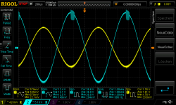
after shortened the bipolar cap the inverted amp worked well. i used exactly the same board for both measurements as described above. first non inverted now inverted.
psu is Rigol DP832
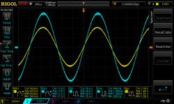
pic 1 inverted amp 25V supply no load_800mVrms in
pic 2 inverted amp 25V supply 8,2R_690mVrms in about 23,5Watt
pic 3 inverted amp 25V supply 8,2R_720mVrms in about 23,5Watt oscillating
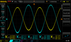
pic 4 inverted amp 25V supply 4,459R_590mVrms in about 31,76Watt ocp kicks in
pic 5 inverted amp 25V supply 4,459R_620mVrms in about 34,48Watt oscillating and ocp kicks in
and...as fred found - with 22V i got (with fan 100mm away from board) no ocp during 4,459R tests.
pic 6 inverted amp 22V supply 4,459R_560mVrms in about 29,15Watt no osc no ocp
pic 7 inverted amp 22V supply 4,459R_570mVrms in about 29,66Watt oscillating
when you compare to the non inverted amp - the inverted is "stronger" and more stable. if i go from oscillating e.g.570mVrms down the sign looks not "wooly" any more.
chris
Thanks you for your help.
after shortened the bipolar cap the inverted amp worked well
. i used exactly the same board for both measurements as described above. first non inverted now inverted.psu is Rigol DP832
pic 1 inverted amp 25V supply no load_800mVrms in
pic 2 inverted amp 25V supply 8,2R_690mVrms in about 23,5Watt
pic 3 inverted amp 25V supply 8,2R_720mVrms in about 23,5Watt oscillating
pic 4 inverted amp 25V supply 4,459R_590mVrms in about 31,76Watt ocp kicks in
pic 5 inverted amp 25V supply 4,459R_620mVrms in about 34,48Watt oscillating and ocp kicks in
and...as fred found - with 22V i got (with fan 100mm away from board) no ocp during 4,459R tests.
pic 6 inverted amp 22V supply 4,459R_560mVrms in about 29,15Watt no osc no ocp
pic 7 inverted amp 22V supply 4,459R_570mVrms in about 29,66Watt oscillating
when you compare to the non inverted amp - the inverted is "stronger" and more stable. if i go from oscillating e.g.570mVrms down the sign looks not "wooly" any more.
chris
Attachments
-
 inverted amp 22V supply 4,459R_570mVrms in about 29,66Watt oscillating.png54.4 KB · Views: 37
 -
 inverted amp 22V supply 4,459R_560mVrms in about 29,15Watt no osc no ocp.png54.2 KB · Views: 35
 -
 inverted amp 25V supply 4,459R_620mVrms in about 34,48Watt oscillating +ocp.png54.7 KB · Views: 203
 -
 inverted amp 25V supply 4,459R_590mVrms in about 31,76Watt ocp.png54.6 KB · Views: 215
 -
 inverted amp 25V supply 8,2R_720mVrms in about 23,5Watt oscillating.png55.6 KB · Views: 209
 -
 inverted amp 25V supply 8,2R_690mVrms in about 23,5Watt.png54 KB · Views: 216
 -
 inverted amp 25V supply no load_800mVrms in.png54.6 KB · Views: 217
Last edited:
Hi Cris,
The flw link is one (of many), describing the inverted versus non-inverted amplifier configs with useful tips.
Inverted-Non-Inverted GC
As far as i can see "our" board layout is well suited with some minor adaptions for the inverted layout as well.
A small tip: the bipolar cap (i used a 47 uF green Muse) does not fit nicely on the standard NFB cap position. However you can simply mount the cap at the 1k NFB position on the board. (And the 1k resistor at the original cap position).
The result is a neat board. In case of an inverted config the 1k resistor can directly be rerouted from the +cap indication to the input plug.
Hi fred
yes the bipolar cap (i use the big green muse 100µF)and the 1k resistor in a non inverting mode could be changed because of better fitting. - good idea
for the last sentence i need eventually more coffee- i don´t catch you
chris
Hi Cris,
Made some photo's which will better explain what i mean.
It was somewhat late yesterday, sorry..
On "photo 1": a finished "non-inverted board", where the feedback (Muse)cap and 1k NFB resistor were swapped. As you can see i could not "nicely" fit the Muse at its original position, but since the cap and 1k are in series, it makes no difference of course to swap them.
i drilled a 0.6 mm hole as you can better see at "photo 2" (upper right at the board). The Muse then is soldered effectively in place of the 1k NFB resistor (at its original position).
For an inverted layout the same idea could eventually be used. Under the assumption that a Muse is used again as input cap see "photo 3".
The input resistor is now directly connected to the input plug as you can see.
Again "photo 4" shows the underside. On the top right you find the Muse and the small hole drilled, to fit and facilitate the mounting of the Muse.
The Muse is mounted partly over the 22k etc. resistors, so solder the Muse as last item of course.
You could use the position of the 330pF cap to mount the pin 1 (+ input) resistor directly to ground.
The yesterday's link gives full guidelines, this resistor should not be omitted. There will be sufficient place on the board to mount a parallel cap to the resistor if noise is an issue. (see yesterday's link)
The question of course arises whether the 1k input resistor could better be increased somewhat to (for instance) 4.7k to improve impedance matching to some pre-amps.
Of course the other feedback resistors should then also be changed. See the yesterday's link for description and guidelines.
Hope i made myself somewhat clearer Cris ...
Very interesting to follow your findings, i have plenty of boards and parts still left and, am also considering to do a trial and test for the inverted config, using this board.
PS It still surprises me l how good this cheap little board actually sounds!
Fred


Made some photo's which will better explain what i mean.
It was somewhat late yesterday
, sorry..On "photo 1": a finished "non-inverted board", where the feedback (Muse)cap and 1k NFB resistor were swapped. As you can see i could not "nicely" fit the Muse at its original position, but since the cap and 1k are in series, it makes no difference of course to swap them.
i drilled a 0.6 mm hole as you can better see at "photo 2" (upper right at the board). The Muse then is soldered effectively in place of the 1k NFB resistor (at its original position).
For an inverted layout the same idea could eventually be used. Under the assumption that a Muse is used again as input cap see "photo 3".
The input resistor is now directly connected to the input plug as you can see.
Again "photo 4" shows the underside. On the top right you find the Muse and the small hole drilled, to fit and facilitate the mounting of the Muse.
The Muse is mounted partly over the 22k etc. resistors, so solder the Muse as last item of course.
You could use the position of the 330pF cap to mount the pin 1 (+ input) resistor directly to ground.
The yesterday's link gives full guidelines, this resistor should not be omitted. There will be sufficient place on the board to mount a parallel cap to the resistor if noise is an issue. (see yesterday's link)
The question of course arises whether the 1k input resistor could better be increased somewhat to (for instance) 4.7k to improve impedance matching to some pre-amps.
Of course the other feedback resistors should then also be changed. See the yesterday's link for description and guidelines.
Hope i made myself somewhat clearer Cris ...
Very interesting to follow your findings, i have plenty of boards and parts still left and, am also considering to do a trial and test for the inverted config, using this board.
PS It still surprises me l how good this cheap little board actually sounds!
Fred
Last edited:
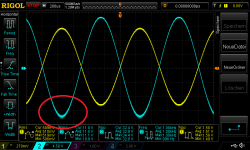
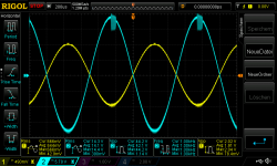
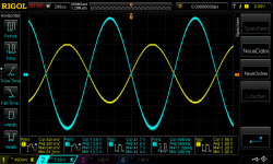
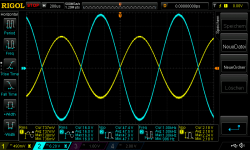
HiCan you zoom in to that area with your scope?
If you increase PSU voltages, does that disappear?
As requested
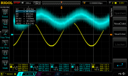
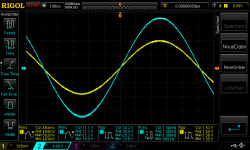
_Yes there is a oscillation at the neg rail nothing at the positive rail.pic 1 inverted amp 22V supply 4,459R_560mVrms in oscillating at negative rail_1
pic 2 inverted amp 22V supply 4,459R_560mVrms in oscillating at negative rail_2
pic 3 inverted amp 22V supply 4,459R_560mVrms in oscillating at negative rail_3
i set my scope to hi resolution
pic 4 inverted amp 22V supply 4,459R_560mVrms in oscillating at negative rail_4_scope hi res
chris
Attachments
-
 inverted amp 22V supply 4,459R_560mVrms in oscillating at negative rail_1.png54.7 KB · Views: 48
 -
 inverted amp 22V supply 4,459R_560mVrms in oscillating at negative rail_2.png47.8 KB · Views: 44
 -
 inverted amp 22V supply 4,459R_560mVrms in oscillating at negative rail_3.png40.3 KB · Views: 48
 -
 inverted amp 22V supply 4,459R_560mVrms in oscillating at negative rail_4_scope hi res.png41.6 KB · Views: 46
Last edited:
- Home
- Amplifiers
- Chip Amps
- eBay mono LM1875 kit