Update tips and hints LM1875 ebay kit
Update: In post 445 i gave my first impressions with the LM1875 ebay kit. Since then i really enjoy listening to this very simple -but remarkably nice sounding- little amplifier.
I was planning to further optimise the components. Actually i now have sufficient selected "quality" parts in house to build a dozen of them...
Every day i am surprised about its excellent sound performance and i can only assume that further refinements will most probably bring only very very minor improvements at best.
If you are interested or considering to make a no-nonsense, simple but very well performing little amplifier read further for guidelines and some photo's of my "beta prototype".
To repeat its main features - which were beyond my expectations:
- The amplifier is very very easy to make.
- it is dead silent, no noise, hiss etc whatsoever. With your ear on the speaker. And remember: No additional delay or relay circuits required.
I presume this is mainly due to the switching on/off characteristics of the special audio class SMPS unit used.
- Further advantages of the Power Supply (300W): its low cost, small size and weight (see attached images)
- The output voltage is stabilised and adjustable between about 21 and 29V. (Badly needed because of the "fake chips" reality)
- output power at +/-24V (the max. allowable for my present version of the "LM1875") is 14.2 V RMS / 25W.
- distortion levels: Using the FFT/ Fourier module on my scope i just can have a general estimate/overview, but not accurately measure the exact %%'s.
It is safe to conclude that distortion is below about 0.1%. I was planning to do more exact distortion measurements, but it is somewhat complicated and
not urgent at this stage since- well.. they sound so nice.
- This replaced my vintage 3x40W Marantz amplifier (incl 1x40W for surround sound effect)
- Contrary to this present- "kit amplifier" my Marantz PM673 was not totally "silent", i had to limit its volume setting to approx 60-65%.
I never could get rid of a slight background/internal loop hum beyond this setting.
- The LM1875 amplifier is superior to my Marantz in all respects. The 2x25W output delivers plenty of loudness.
- Also i further noticed that a large heat sink is really not required.
Of course i initially started with an oversized heat sink, but soon came to the conclusion it is sort of "overkill".
Finally i simply mounted the LM1875 (fake) -chips directly on the 2 mm aluminium base plate with good results.
To my surprise the temp (measured) is not exceeding 35 degrees C, also after playing music for several hours at moderate to loud levels.
- A general remark: The quality of the boards is adequate, the layout is excellent. But they are not made to experiment and definitely not for frequent
soldering.
Reliability is severely questionable after replacing components, multiple soldering, making changes etc.
Buy several copies, use one copy for testing, component selection etc and then make your final version on a new/fresh pcb (final is final: preferably do not
change for max long term reliability)
All in all this is an excellent amplifier and amazingly simple, mainly thanks to the (audio-quality) SMPS power supply.
If you are still in doubt for a SMPS, an interesting and convincing article to read is "Audio myth: Switching power supplies are noisy" (Click here > ) "Audio myth: Switching power supplies are noisy"
Building (example).
Look in 5 steps how simple it can be:
Fig 1
I selected a 15 Eur black alu case (see post 445 for further info). Size approx 22x14.4x5 cm. As you will see later the case could even be much smaller for a standard stereo version.
The original "base plate" of this case was kept unused for the time being. It will be used later in the "final" setup.
Instead i made a temp. 2 mm replacement Alu base plate P2 and a smaller Alu piece P1
Fig 2
The SMTP was mounted on 6 mm spacers (to enable 220 V and +/- 25 V cabling beneath the SMTP unit. The P1 plate is mounted vertically with 8 mm spacers on the (standard built-in) 3 mm fixing-bolts of the SMTP.
Fig 3
Here you can see the cable routing and pcb preparation (220V to the left)
Please note that the amplifiers boards can be mounted very close to the power supply.
Remember there is no- or very little magnetic interference compared to traditional transformers.
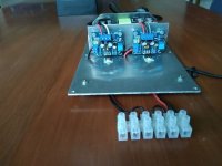
Fig 4
Next image shows the "wired" amplifier
Note its compactness. Wiring is between the Alu plate P1 and Alu SMPS case and beneath the power supply unit.
All wiring is so to say in "screened corridors" of Alu walls.
Also note, that as mentioned above no special - or heavy heat sinks were required.
I tested the present setup thoroughly under normal use (several hours loud to moderate sound levels) and temps are stabilising at under 35 degrees C.
Sine-wave testing the amps during a limited time at full load, just under clipping (about 14.5 V RMS at 8 ohms and 25 W of output) is no problem.
Of course the aluminium base plate is then quickly heating up, so don't do this for extended periods (or use a temp. fan). During such testing preferably use one amplifier at a time at full load.
Don't forget to check the output voltage offset before connecting your speakers.
Fig 5
The amplifier is finished. For this beta version a simple LS connection block is used. Notice that a third speaker set can be used for a rear "Haffler surround sound effect" . This speaker set is wired to the L/R "hot" speaker connections of the two L/R amplifiers. No stability problems. Of course it is just an option, i simply like a " surround" effect.. Later on (in its final version) i will use a third LM1875 amplifier and surround processing pcb for which sufficient space is available/reserved as you can see.
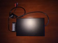
Fig 6
The closed black box.
The box directly connects to my Teufel streaming device (supports FLAC). It is placed somewhere out of sight and music selection - volume etc is remotely controlled by an app on phone or tablet . Music library is on NAS.
My intention was to keep things simple and no-nonsense but without doing concessions to sound quality.
Next step will be to build the final version using higher quality components .
Difficult to imagine,however, it will bring me a major improvement.
Also i am following the other "composite" thread with much interest.
Initially i was considering a composite or higher output version, but well.. it looks like this little amplifier is really good enough to enjoy listening to my favourite music (classic - full orchestral Bruckner -Wagner etc) . Demanding music for an amplifier and speakers.
For newcomers my advise is to consider using this 300W (or similar) SMPS.
At least i am convinced, the advantages are many and obvious ...
PS The quality of the photo's is by no means an indication of the amplifier's sound quality!
Success, Fred
Update: In post 445 i gave my first impressions with the LM1875 ebay kit. Since then i really enjoy listening to this very simple -but remarkably nice sounding- little amplifier.
I was planning to further optimise the components. Actually i now have sufficient selected "quality" parts in house to build a dozen of them...
Every day i am surprised about its excellent sound performance and i can only assume that further refinements will most probably bring only very very minor improvements at best.
If you are interested or considering to make a no-nonsense, simple but very well performing little amplifier read further for guidelines and some photo's of my "beta prototype".
To repeat its main features - which were beyond my expectations:
- The amplifier is very very easy to make.
- it is dead silent, no noise, hiss etc whatsoever. With your ear on the speaker. And remember: No additional delay or relay circuits required.
I presume this is mainly due to the switching on/off characteristics of the special audio class SMPS unit used.
- Further advantages of the Power Supply (300W): its low cost, small size and weight (see attached images)
- The output voltage is stabilised and adjustable between about 21 and 29V. (Badly needed because of the "fake chips" reality)
- output power at +/-24V (the max. allowable for my present version of the "LM1875") is 14.2 V RMS / 25W.
- distortion levels: Using the FFT/ Fourier module on my scope i just can have a general estimate/overview, but not accurately measure the exact %%'s.
It is safe to conclude that distortion is below about 0.1%. I was planning to do more exact distortion measurements, but it is somewhat complicated and
not urgent at this stage since- well.. they sound so nice.
- This replaced my vintage 3x40W Marantz amplifier (incl 1x40W for surround sound effect)
- Contrary to this present- "kit amplifier" my Marantz PM673 was not totally "silent", i had to limit its volume setting to approx 60-65%.
I never could get rid of a slight background/internal loop hum beyond this setting.
- The LM1875 amplifier is superior to my Marantz in all respects. The 2x25W output delivers plenty of loudness.
- Also i further noticed that a large heat sink is really not required.
Of course i initially started with an oversized heat sink, but soon came to the conclusion it is sort of "overkill".
Finally i simply mounted the LM1875 (fake) -chips directly on the 2 mm aluminium base plate with good results.
To my surprise the temp (measured) is not exceeding 35 degrees C, also after playing music for several hours at moderate to loud levels.
- A general remark: The quality of the boards is adequate, the layout is excellent. But they are not made to experiment and definitely not for frequent
soldering.
Reliability is severely questionable after replacing components, multiple soldering, making changes etc.
Buy several copies, use one copy for testing, component selection etc and then make your final version on a new/fresh pcb (final is final: preferably do not
change for max long term reliability)
All in all this is an excellent amplifier and amazingly simple, mainly thanks to the (audio-quality) SMPS power supply.
If you are still in doubt for a SMPS, an interesting and convincing article to read is "Audio myth: Switching power supplies are noisy" (Click here > ) "Audio myth: Switching power supplies are noisy"
Building (example).
Look in 5 steps how simple it can be:
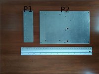
Fig 1
I selected a 15 Eur black alu case (see post 445 for further info). Size approx 22x14.4x5 cm. As you will see later the case could even be much smaller for a standard stereo version.
The original "base plate" of this case was kept unused for the time being. It will be used later in the "final" setup.
Instead i made a temp. 2 mm replacement Alu base plate P2 and a smaller Alu piece P1
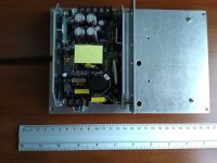
Fig 2
The SMTP was mounted on 6 mm spacers (to enable 220 V and +/- 25 V cabling beneath the SMTP unit. The P1 plate is mounted vertically with 8 mm spacers on the (standard built-in) 3 mm fixing-bolts of the SMTP.
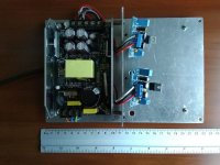
Fig 3
Here you can see the cable routing and pcb preparation (220V to the left)
Please note that the amplifiers boards can be mounted very close to the power supply.
Remember there is no- or very little magnetic interference compared to traditional transformers.
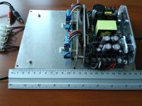
Fig 4
Next image shows the "wired" amplifier
Note its compactness. Wiring is between the Alu plate P1 and Alu SMPS case and beneath the power supply unit.
All wiring is so to say in "screened corridors" of Alu walls.
Also note, that as mentioned above no special - or heavy heat sinks were required.
I tested the present setup thoroughly under normal use (several hours loud to moderate sound levels) and temps are stabilising at under 35 degrees C.
Sine-wave testing the amps during a limited time at full load, just under clipping (about 14.5 V RMS at 8 ohms and 25 W of output) is no problem.
Of course the aluminium base plate is then quickly heating up, so don't do this for extended periods (or use a temp. fan). During such testing preferably use one amplifier at a time at full load.
Don't forget to check the output voltage offset before connecting your speakers.
Fig 5
The amplifier is finished. For this beta version a simple LS connection block is used. Notice that a third speaker set can be used for a rear "Haffler surround sound effect" . This speaker set is wired to the L/R "hot" speaker connections of the two L/R amplifiers. No stability problems. Of course it is just an option, i simply like a " surround" effect.. Later on (in its final version) i will use a third LM1875 amplifier and surround processing pcb for which sufficient space is available/reserved as you can see.
Fig 6
The closed black box.
The box directly connects to my Teufel streaming device (supports FLAC). It is placed somewhere out of sight and music selection - volume etc is remotely controlled by an app on phone or tablet . Music library is on NAS.
My intention was to keep things simple and no-nonsense but without doing concessions to sound quality.
Next step will be to build the final version using higher quality components .
Difficult to imagine,however, it will bring me a major improvement.
Also i am following the other "composite" thread with much interest.
Initially i was considering a composite or higher output version, but well.. it looks like this little amplifier is really good enough to enjoy listening to my favourite music (classic - full orchestral Bruckner -Wagner etc) . Demanding music for an amplifier and speakers.
For newcomers my advise is to consider using this 300W (or similar) SMPS.
At least i am convinced, the advantages are many and obvious ...
PS The quality of the photo's is by no means an indication of the amplifier's sound quality!
Success, Fred
Attachments
Last edited:
Fred, it is a super report.
Not only is the description of the (subjective) impression so convincing that it should encourage many who see no need for a high power amplifier to join this project. It also gives such advise that it is difficult to fail.
Genius is to get a lot out of a little. You have described how that can be obtained.
Thank you FauxFrench for your nice words. This is a good time to also express my appreciation for your many professional contributions to the forum.
Actually you are a great "people's motivator".
It's great to see how you are motivating people with some to-the-point professional recommendations/directions. Always in a positive sense with some social or nice words!
@Rabbitz, thanks too, yes it is fun and what amazed me above all is how this little device performs in comparison to my Marantz PM673 set.
This was really an expensive set at the time. Out of the Japanese golden audio century (90's).
If opening the unit you immediately realize: his is a technological power house. Beautifully engineered, first class components - but.. so complicated you almost don't want to touch it. All functions microprocessor controlled , a heavy and large case and full of PCB's and electronics connected by flat cables etc.
If you want to -or must- take it apart you realize.. it will be difficult to bring it back in its original state.
Despite all this sophistication i had a disturbing internal hum / ground loop which i tried (several times) to carefully repair. Well i gave up because i did not want to take the unit apart totally. Also checked but no el-capacitors problems.
Fortunately at a 60-65% volume setting it was ok, so that's how i used the Marantz for years.
Is it not amazing? .. that when i turned on the "LM1875" amplifier for the first time, i immediately noticed a superior open sound, better bass and complete silence from this cheap little DIY set..
People i demonstrated the set to all agreed its superiority in blind tests.
So yes it gave me much enjoyment and fun indeed!
Last edited:

Thank you for your help everyone, it looks like I’ll follow Freds build. Wonderful detail in that description. With this unit (mine is the same but accepts 88~264 VAC) would it be possible to power VU meters as well or should I consider the SMPS300R which has an auxiliary voltage? I’m not enthusiastic about that solution as it costs twice as much and doesn’t have the heat shield.
Thanks for the appreciation everyone!
@Philz81, Yes you're right the power supply i used is not suitable for my US friends.
Instead there is an almost identical unit, which accepts an input voltage of 88~264VAC.
It also delivers regulated output voltages: +15V GND -15V / current: 1A and DC12V / current: 1A (e.g. fan , Bluetooth device and probably your power VU meters).
Here is a direct link >>: Power Supply 88~264VAC
However it looks like a var. resistor is missing to adjust the main 5A +/-24V output. (in my case the main voltage is adjustable between +/- 21-29V).
In other words this power supply is probably not adjustable (fixed +/-24V?), which i consider a drawback.
Note: On the powersupply, which i am actually using, there is an regulated output of 12V (1A) availabe, which is not used in my case. (in my posting Fig 4 at position "14.5" of the ruler; the var resistor is at pos "19")
Although most (fake) "LM1875" chips are ok with +/-24 V, if you are lucky and receive (or can obtain) genuine LM1875 chips, you obviously could obtain an increased output wattage with 2x28V.
On YouTube there are some interesting presentations with valuable info (look for JohnAudioTech and LM1875).
He reports about 30W of clean power at 28V @8 Ohms.
Please check with the supplier, i might be wrong.
PS if you are interested i can post or send a 1:1 drilling template of the Alu sheets
Fred
Last edited:
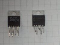
For the future, here's another comparison Ebay vs Digikey picture.
Ebay chip on the left, most likely fake but un-tested.
Digikey chip on the right.
Edit: for some reason the pic got rotated, I'm sorry. Fake chip on the bottom if you're looking at it sideways haha
Ebay chip on the left, most likely fake but un-tested.
Digikey chip on the right.
Edit: for some reason the pic got rotated, I'm sorry. Fake chip on the bottom if you're looking at it sideways haha
Attachments
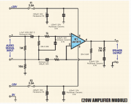
I am looking to build this amp. Is there a concise listing of all the parts needed? I found a detailed list on pot #442 and was wondering if there was more. Specifically I am interested in the maximum voltage for the transformer. I see 18V often but was wondering if it was acceptable to go higher. TIA.
I am looking to build this amp. Is there a concise listing of all the parts needed? I found a detailed list on pot #442 and was wondering if there was more. Specifically I am interested in the maximum voltage for the transformer. I see 18V often but was wondering if it was acceptable to go higher. TIA.
Hi theaddies
the maximum Voltage +/- of this chip amp is according to the datasheet +/-30V.
A transformer with 18 -0- 18VAC give you after rectifier and cap bank about 26,8V DC at each rail in idle mode and thats the maximum voltage that most people use for 8 ohm loads(speakers impedance). if you need more power you can look at the Lm1875 parallel composite amp thread or you choose another chip - more current/power with lm1875 is not so easy...
Please look again the complete thread to choose your components by rabbitz or other builder. rabbitz is an experianced amp builder and he stated that if you need more power its better to choose a stronger chip. but believe me the lm1875/and TDA2050 are really powerful for home use about 20W - 30W at 8ohms speaker.
")
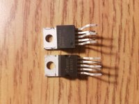
the board what you get by ebay/aliexpress/amazon are not bad in general.
here are some examples i collected during my journey
:chris
Attachments
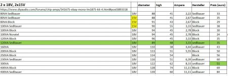
Wow, that's fantastic. Thanks very much for the information. As far as the toroidal transformer is concerned I don't suppose there is any benefit to exceeding a load of 50VA? I found this transformer on Parts Express that also comes in a 160VA version. Would these simply be overkill or would they not work? Thanks again for the response.
Wow, that's fantastic. Thanks very much for the information. As far as the toroidal transformer is concerned I don't suppose there is any benefit to exceeding a load of 50VA? I found this transformer on Parts Express that also comes in a 160VA version. Would these simply be overkill or would they not work? Thanks again for the response.
Hi
50VA each channel should be ok. i planned a power supply for my mock up and future amps with a 120VA/18VAC for both channels and its really enough and it was cheap...about 35euro new. if you want to build an amp think about your enclosure and therefore about the components inside.
here is an idea about some dimensions of some transformers...i looked at conrad and other shops in my countryonce again...take your time and read and note some points for your ideas....the complete thread...chris
Attachments
Last edited:
Pardon the newb question, but should the LM1875 be electrically isolated from the case/heasink?
Thanks,
yes..if the heat sink is connected to the chassis.
pin 3 (-V) is connected to the mounting plate of the LM1875
chris
Edit: is this even in the datasheet? I didn't spot it.
.........page 8 and 9 in the tex. inst. data sheet........:
NOTE
When using a single supply, maximum transfer of heat away from the LM1875 can be
achieved by mounting the device directly to the heat sink (tab is at ground potential); this
avoids the use of a mica or other type insulator.
- Home
- Amplifiers
- Chip Amps
- eBay mono LM1875 kit