Did all the swapping R to L etc all the way through. Not a problem as it's pulled apart and have moved on.
 ...sorry
ask ESP directly?
chris
Not worth the effort as it was never going to be used as I have too many not being used. I've built over 30 SS amps and this is the only one that beat me.
30 : 1 is a very good quote !!
Last edited:
...measurments with caps at the speakers terminal
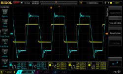
Hi
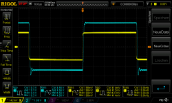
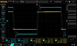
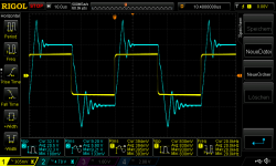
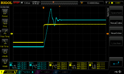
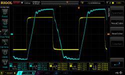
i was motivated to try a square wave test at my listening "mock up amp".
i use a 220nF at one channel to look at . the cap is a grey Kemet 220nF MKP X2 / 275VAC load is 8R non inductive on both channel.
its about 10,8 Watt each channel
pic 1 200mVrms in square 10khz_220nF
pic 2 200mVrms in square 20khz_220nF
pic 3 400mVrms in square 10khz_220nF
pic 4 400mVrms in square 20khz_220nF
oscillating..
pic 5 700mVrms in square 10khz_220nF
pic 6 700mVrms in square 20khz_220nF
after this bad oscillating i will not do 4R test with max power...
some comments or ideas?
chris
Hi
i was motivated to try a square wave test at my listening "mock up amp".
i use a 220nF at one channel to look at . the cap is a grey Kemet 220nF MKP X2 / 275VAC load is 8R non inductive on both channel.
its about 10,8 Watt each channel
pic 1 200mVrms in square 10khz_220nF
pic 2 200mVrms in square 20khz_220nF
pic 3 400mVrms in square 10khz_220nF
pic 4 400mVrms in square 20khz_220nF
oscillating..
pic 5 700mVrms in square 10khz_220nF
pic 6 700mVrms in square 20khz_220nF
after this bad oscillating i will not do 4R test with max power...
some comments or ideas?
chris
Attachments
-
 200mVrms in square 10khz_220nF.png43.6 KB · Views: 228
 -
 200mVrms in square 20khz_220nF.png46.9 KB · Views: 229
 -
 400mVrms in square 10khz_220nF.png45.4 KB · Views: 235
 -
 400mVrms in square 20khz_220nF.png49.6 KB · Views: 234
 -
 700mVrms in square 10khz_220nF_ringing.png45 KB · Views: 237
 -
 700mVrms in square 20khz_220nF_ringing.png47 KB · Views: 52
Last edited:
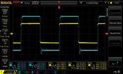
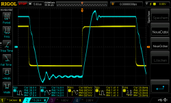
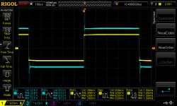
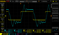
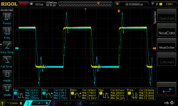
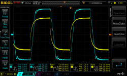
its gooing worse with 440nF
here is the same test but i try the other channel - L channel but with 440nF...same cap type.
now with just 200mVrms at 8R its about 2,6Watt per channel
pic1 200mVrms in square 1khz_440nF_L channel
pic2 200mVrms in square 1khz_440nF_L channel_2
pic3 200mVrms in square 10khz_440nF_L channel
pic4 200mVrms in square 20khz_440nF_L channel
pic5 200mVrms in square 30khz_440nF_L channel
Attachments
-
 200mVrms in square 30khz_440nF_L channel.png54.3 KB · Views: 49
 -
 200mVrms in square 20khz_440nF_L channel.png49.4 KB · Views: 46
 -
 200mVrms in square 10khz_440nF_L channel.png45.4 KB · Views: 42
 -
 200mVrms in square 1khz_440nF_L channel_2.png43.4 KB · Views: 50
 -
 200mVrms in square 1khz_440nF_L channel.png42.9 KB · Views: 55
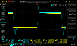
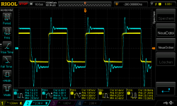
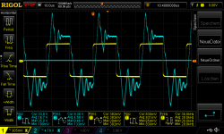
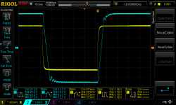
...bad at 440nF and 400mVrms input
pic1 400mVrms in square 1khz_440nF_L channel
pic2 400mVrms in square 1khz_440nF_L channel_2
pic3 400mVrms in square 10khz_440nF_L channel
pic4 400mVrms in square 20khz_440nF_L channel
pic5 400mVrms in square 30khz_440nF_L channel
its about 10,5 Watt at 8R
pic1 400mVrms in square 1khz_440nF_L channel
pic2 400mVrms in square 1khz_440nF_L channel_2
pic3 400mVrms in square 10khz_440nF_L channel
pic4 400mVrms in square 20khz_440nF_L channel
pic5 400mVrms in square 30khz_440nF_L channel
its about 10,5 Watt at 8R
Attachments
-
 400mVrms in square 30khz_440nF_L channel.png47.1 KB · Views: 44
 -
 400mVrms in square 20khz_440nF_L channel.png51.2 KB · Views: 39
 -
 400mVrms in square 10khz_440nF_L channel.png49.2 KB · Views: 36
 -
 400mVrms in square 1khz_440nF_L channel_2.png40.5 KB · Views: 38
 -
 400mVrms in square 1khz_440nF_L channel.png42.6 KB · Views: 48
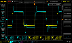
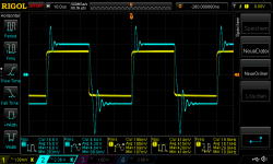
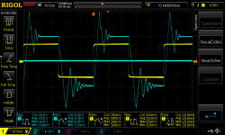
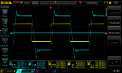
As i wrote i listening since weeks and i found to use a "zobel 220nF +10R" at the speakers output as better sound.
the only way i can explain "technically" is a comparison. no zobel is the swing bigger = overshoot and it is a longer swing
pic1 400mVrms in square 10khz_440nF_L channel
pic2 400mVrms in square 10khz_440nF_L channel - no zobel
pic3 400mVrms in square 20khz_440nF_L channel
pic4 400mVrms in square 20khz_440nF_L channel - no zobel
pic5 400mVrms in square 30khz_440nF_L channel
pic6 400mVrms in square 30khz_440nF_L channel - no zobel
chris
Attachments
-
 400mVrms in square 30khz_440nF_L channel_no zobel.png62 KB · Views: 47
 -
 400mVrms in square 30khz_440nF_L channel.png47.1 KB · Views: 38
 -
 400mVrms in square 20khz_440nF_L channel_no zobel.png53.9 KB · Views: 37
 -
 400mVrms in square 20khz_440nF_L channel.png51.2 KB · Views: 43
 -
 400mVrms in square 10khz_440nF_L channel_no zobel.png50.2 KB · Views: 42
 -
 400mVrms in square 10khz_440nF_L channel.png49.2 KB · Views: 45
I ´d play around with max power test - i use a 100hZ tone.
here some compare data´s sinus vs square wave
no caps on the speakers just the zobel and the non inductive 8R.
sinus max input is 600mVrms = 40,4Vpp and 13,8Vrms at 8R its about 24Watt
the rails are in idle at my amp +/- 26,6V = 53,2V
during this max test i get a non sync. rail voltage drop with 23V and 23,3V = 46,3 i loose 6,9Volts.
square test is harder - but i was able to "climb" to the rail nearer...
max input is 900mVrms square = 42,5Vpp and 19,6Vrms at 8R its about 48Watt
the rails are in idle at my amp +/- 26,6V = 53,2V
during this max test i get a non sync. rail voltage drop with 21,7V and 22,1V = 43,8 i loose 9,4Volts.
chris
good night
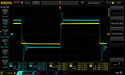
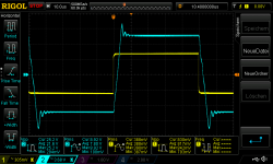
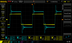
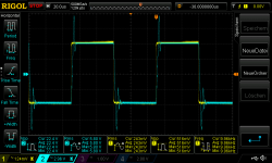
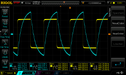
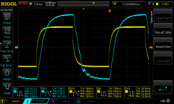
...avoi oscillation..method 1 . add 47pF at feedback
Hi
i am not sure if this is the best method but i solder a 47pF cap in parallel to the 22k Feedback resistor. any other hints are very welcome.
R channel input is 400mVrms into 8R and the 440nF cap on the speaker terminal.
pic 1 400mVrms in square 10khz_440nF_R channel
pic 2 400mVrms in square 10khz_440nF_R channel + 47pF feedback
pic 3 400mVrms in square 20khz_440nF_R channel
pic 4 400mVrms in square 20khz_440nF_R channel + 47pF feedback
pic 5 400mVrms in square 30khz_440nF_R channel
pic 6 400mVrms in square 30khz_440nF_R channel + 47pF feedback
any comments/ideas ?
chris
Attachments
-
 400mVrms in square 30khz_440nF_R channel_47pF feeback.png54.4 KB · Views: 48
 -
 400mVrms in square 30khz_440nF_L channel.png47.1 KB · Views: 45
 -
 400mVrms in square 20khz_440nF_R channel_47pF feedback.png51.3 KB · Views: 47
 -
 400mVrms in square 20khz_440nF_L channel.png51.2 KB · Views: 45
 -
 400mVrms in square 10khz_440nF_R channel_47pF feedback.png45.1 KB · Views: 40
 -
 400mVrms in square 10khz_440nF_L channel.png49.2 KB · Views: 44
recovered chips cannot do the same performance?
Hi
i want to try this square wave test on the other boards too. this boards are with the 1875 recovered - shortcut survived. the test is with my lab psu set to 27V, 3A each rail. 250mV is the maximum because after some seconds a kind of protection mode kicks in! every 2,5 seconds the chip is switching on/off.
pic 1 this is the board i tested.
pic 2 250mVrms square in 10kHz at 8R + 440nF cap
pic 3 250mVrms square in 20kHz at 8R + 440nF cap
pic 4 250mVrms square in 30kHz at 8R + 440nF cap
pic 5 show you with a long time set that every 2,5 seconds the chip is switching off -my psu shows me that the voltages drops to zero.
this phenomenon i get just at the other amp with max power and high frequency. so for me this chip actually are not 100% "recovered"
do somebody have the same experience??
chris
Attachments
-
 protection mode every 3 seconds.png44.1 KB · Views: 223
 -
 200mVrms square in 30kHz at 8R + 440nF cap.png57.3 KB · Views: 223
 -
 200mVrms square in 20kHz at 8R + 440nF cap.png48.7 KB · Views: 230
 -
 200mVrms square in 10kHz at 8R + 440nF cap.png48.2 KB · Views: 224
 -
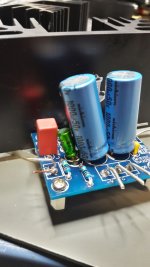 4µ7wima22µES_1000µFrail_1.jpg214.4 KB · Views: 233
Comment: Reducing bandwidth (47pF) seems to improve stability margin.
Idea: Try with 220pF instead of the 47pF.
Hello FF
Thank you for your advice ! ...i will do so.
chris
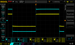
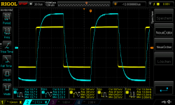
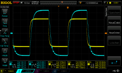
..220pf at the feedback
Hi
here is the result at my mock up amp. i did the test with 400mvrms into 8R and 440nF cap at the R channels output. L channel just 8R.
400mVrms in square 10khz_440nF_R channel_220pF feedback
400mVrms in square 20khz_440nF_R channel_220pF feedback
400mVrms in square 30khz_440nF_R channel_220pF feedback
chris
Attachments
Hi
here is the result at my mock up amp. i did the test with 400mvrms into 8R and 440nF cap at the R channels output. L channel just 8R.
400mVrms in square 10khz_440nF_R channel_220pF feedback
400mVrms in square 20khz_440nF_R channel_220pF feedback
400mVrms in square 30khz_440nF_R channel_220pF feedback
chris
Many thanks.
Too slow, 100pF should be right. Eventually, try to hear if you notice the difference between no capacitor and 100pF with music.
Hi FF
Actually i listening with 220pf at the feedback about 2.5 hours and compare to my TPA3255.
the lm 1875 is now a different - better amp - its clear and deeper sound stage, partly i go through some older album and its sounds very very nice.
nevertheless i will modify the cap to the 100pf to get faster response...
thanks
chris
Actually i listening with 220pf at the feedback about 2.5 hours and compare to my TPA3255.
the lm 1875 is now a different - better amp
- its clear and deeper sound stage, partly i go through some older album and its sounds very very nice.nevertheless i will modify the cap to the 100pf to get faster response...
thanks
chris
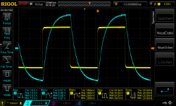
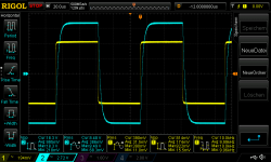
...100pf in the feedback
Good morning
here is the test with my mock up amp (amp 1_2) with the feedback cap of 100pf each channel. test is with 8R and the Rchannel is the 440nF cap load added.
pic 1 400mVrms in square 10khz_440nF_R channel 100pF feedback
pic 2 400mVrms in square 20khz_440nF_R channel 100pF feedback
pic 3 400mVrms in square 30khz_440nF_R channel 100pF feedback
i tried 600mVvrms in ..it is stable
pic 4 600mVrms in square 10khz_440nF_R channel 100pF feedback
pic 5 600mVrms in square 20khz_440nF_R channel 100pF feedback
pic 6 600mVrms in square 10khz_440nF_R channel 100pF feedback
listening not done...(kefQ100)
as i wrote the post before - the sound - with 220pf - was very dynamic and clear without "noise/fog " in the background. the details get much better without harshness or bad high snake t,z,s..
chris
Attachments
-
 600mVrms in square 30khz_440nF_R channel 100pF feedback.png50.4 KB · Views: 42
 -
 600mVrms in square 20khz_440nF_R channel 100pF feedback.png52.3 KB · Views: 50
 -
 600mVrms in square 10khz_440nF_R channel 100pF feedback.png43.9 KB · Views: 44
 -
 400mVrms in square 30khz_440nF_R channel 100pF feedback.png48.1 KB · Views: 46
 -
 400mVrms in square 20khz_440nF_R channel 100pF feedback.png49 KB · Views: 58
 -
 400mVrms in square 10khz_440nF_R channel 100pF feedback.png48.3 KB · Views: 44
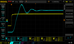
frequence response with 8R and 4R resistive load
Good morning
after all this changes i did a frequency response with resistive load 8R and 4R. input is 10mmVrms and that´s about 0,7W @8R and 1,3W @ 4R.
its a soft roll off of the gain of 27db nearly the same for 8R or 4R
17khz -0,3dB
23khz -0,5dB
31khz -1dB
47khz -2db
59khz -3db
chris
Good morning
after all this changes i did a frequency response with resistive load 8R and 4R. input is 10mmVrms and that´s about 0,7W @8R and 1,3W @ 4R.
its a soft roll off of the gain of 27db nearly the same for 8R or 4R
17khz -0,3dB
23khz -0,5dB
31khz -1dB
47khz -2db
59khz -3db
chris
Attachments
- Home
- Amplifiers
- Chip Amps
- eBay mono LM1875 kit