I saw this old post by jcx many years ago and was wondering if anyone has tried
something similar with the LM3886 or any power OP amp:
https://www.diyaudio.com/forums/solid-state/125317-easiest-build-class.html#post1546823
R1 and R2 would be .1 to .5 ohms of course, and they might have to be setup for
more gain.
Also would have twice the output current capability.
Anyone tried it?
Seems difficult. First of all the LM3886 is decompensated and can't be run at unity gain like the circuit you linked. So you'll need extremely well matched resistors to set the gain=10.00 of each one. Second, the ballasting resistors R1 and R2 probably need to be less than 15 ohms if you're driving a 4 ohm loudspeaker at the output. This means the class-A bias current (=Vdiode/(R1+R2)) will be uncomfortably large unless you abandon the diode and build a precision level shifter with a much smaller voltage drop.
Haven't tried it myself.
Haven't tried it myself.
Attachments
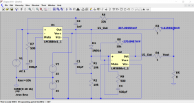
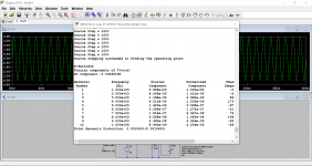
With +/- 35V supplies that's ~13 watts of class A dissipation in each of the two LM3886's. Gulp!
In the left chip U1 the output stage pullup carries 370mA more current than the pulldown.
In the right chip U2 the output stage pulldown carries 370mA more current than the pullup.
In the left chip U1 the output stage pullup carries 370mA more current than the pulldown.
In the right chip U2 the output stage pulldown carries 370mA more current than the pullup.
") gulp indeed.
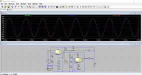
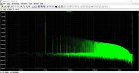
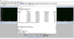
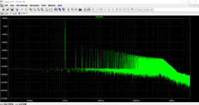
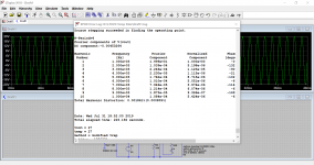
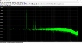
gulp indeed.This shows the set up with the two chips (first images) and then just one chip used normally. So it does kind of lower distortion. I also should have used a more appropriate value for the 1nF.
The FFT shows 'odds' predominate in the twin chip version.
Attachments
... Second, the ballasting resistors R1 and R2 probably need to be less than 15 ohms if you're driving a 4 ohm loudspeaker at the output.
unless you abandon the diode and build a precision level shifter with a much smaller voltage drop.
Haven't tried it myself.
Did you even bother to read my post, I suggested .1 - .5 ohms for those resistors in a power
amp application. Yes, it would need to be designed for more than unity gain, and of course
the diode bias would be adjusted to get whatever level of class A bias that one wants within
the capability of the part and heatsinking.
@Mooly nice work on the sims, thanks!
Last edited:
and of course the diode bias would be adjusted to get whatever level of class A bias that one wants within the capability of the part and heatsinking.
Mooly adjusted the diode bias by: doing nothing. The cost was 13 watts in each of two LM3886's. The benefit was: simplicity. It functioned properly in simulation.
Another possible adjustment is to use a high precision shunt voltage reference IC such as the LM4040AIZ-1.2 (thru hole packaging, ±0.1% tolerance, 1.225V, max current = 25mA, $1.87 qty=1) instead of a diode, with a high precision resistive voltage divider, to select exactly abc.de% of 1.25V as the levelshift amount. This chip is on the shelf at DigiKey (link) and Octopart.com can tell you where else it's available. Tune the class-A quiescent power dissipation to whatever number you wish, merely by twirling the shaft of a 25-turn trimmer potentiometer.
Haven't done this myself.
Once upon a time, I fooled around with two tda2030 and a Vdiff at the inputs, and of course gain in the nfb. Too fiddly with the nfb (for me); a chipamp isn't behaving like a normal opamp in this regard.
A simplification would be to "attach" a CCS to the output of a chipamp. For example with a single-ended cap-coupled tda2030 amp, you just need to add a to220 PNP current sink to the output, and there you go. PNP to220 tab goes directly to gnd; can be fixed directly to the heatsink just like the chipamp. Cheaper, faster, smaller, less trouble.
A simplification would be to "attach" a CCS to the output of a chipamp. For example with a single-ended cap-coupled tda2030 amp, you just need to add a to220 PNP current sink to the output, and there you go. PNP to220 tab goes directly to gnd; can be fixed directly to the heatsink just like the chipamp. Cheaper, faster, smaller, less trouble.
A simplification would be to "attach" a CCS to the output of a chipamp. For example with a single-ended cap-coupled tda2030 amp, you just need to add a to220 PNP current sink to the output, and there you go. PNP to220 tab goes directly to gnd; can be fixed directly to the heatsink just like the chipamp. Cheaper, faster, smaller, less trouble.
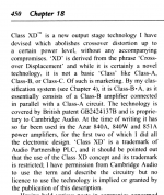
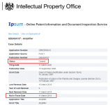
Sounds a lot like Douglas Self's "XD" crossover displacement. The patent appears to have "ceased" / "expired" .
_
Attachments
anyone with experience of the 3886 cm range in unity gain? (with noise gain compensation)
the data sheet cmrr spec seems to have been measured with +/-20 V and 80 V total supply
which would need a audio frequency gain of 2 (not unreasonable as DC gain - lots matched value resistors, not too high a Vos multiple)
I'm not likely to add a lot to this thread, or be very responsive since shingles ripped up nerves in my right arm and the pain management drugs don't seem good for concentration
get the new Shingrix vax - recommended now for those over 50
I'm doing the opposite -- building Cordell's "Super Gain Clone" which operates the LM3886 in inverting mode, thereby guaranteeing the common mode input is zero. It appears to work just fine. I haven't yet horsed around with un-socketing the DC servo chip to see what kind of DC offset it may have before nullification.
- Status
- This old topic is closed. If you want to reopen this topic, contact a moderator using the "Report Post" button.
- Home
- Amplifiers
- Chip Amps
- High Bias LM3886 anyone?