I'm in the process of (re)building a three channel LM3886 amp which uses two single LM3886 PCBs for the left/right mid/high channels & one dual (parallel) LM3886 PCB for the sub channel.
My previous LM3886 used the single XY boards with no problems, but this time round I went for the boards from KMTech as he sells single boards, parallel boards & an active crossover board. I've run into a number of issues with them however, namely that the position of the thru-holes for the LM3886 are too far from the edge of the PCB so the ICs don't sit flat against the heatsink (I've come across another post here on the forums from somebody who ran into the same issue) & with the parallel board the mute circuitry isn't actually implemented & the board has to be modified to make the amp actually make noise.
At this stage I honestly just want to drop the KMTech boards & start afresh with stuff that actually works from the get go, rather than try to file down the PCBs, tack the mute circuitry onto the IC on the bottom of the board, etc. So what right now are the de facto 'good' PCBs for individual & parallel (two IC) LM3886 boards? I don't mind if it's something I can buy on eBay/AliExpress or a community design that I can order to get made from JLCPCB.
You can consider my LM3886 Done Right. Or, if you prefer truly stellar performance, my Modulus series. The Modulus amps use error correction to eliminate the distortion caused by the LM3886. My Modulus-286 uses two LM3886es for higher output power and employs error correction as well. For even higher output power, I offer the Modulus-686. You'll get nearly 400 W into 4 Ω at about -120 dB THD. For a "safe-n-sane" build, you can lower the supply voltage a bit and get, say, 125 W (8 Ω), 200 W (4 Ω) without much fuss.
Tom
Tom
I'm offering this bit of info for you purely based off of listening to the Modulus-686 amps with the LXmini setup at Burning amp last year, and based on tomchr's work put into them- they are one of the best amplifiers I have ever heard, period. Either of his designs based on the 3886 would be fantastic, but it just depends on your budget.
I'm a die-hard tube guy but I still heartily recommend the Neurochrome stuff to anybody interested in building solid state amplification. I even added a few genuine TI 3886 IC's to the kits he put in the raffle at burning amp last year")
I'm a die-hard tube guy but I still heartily recommend the Neurochrome stuff to anybody interested in building solid state amplification. I even added a few genuine TI 3886 IC's to the kits he put in the raffle at burning amp last year
Strangely, there aren't many parallel boards floating around. You could always build single boards with 0.1% resistors to set the gain and just add 0.22r output resistors to balance things out.
As posted above, the modulus serie is really the best you can get with chipamps. If you're looking for something more pedestrian, maybe have a look here: An open source LM3886 chip amplifier. – (mis) Adventures in Hi-Fi
As posted above, the modulus serie is really the best you can get with chipamps. If you're looking for something more pedestrian, maybe have a look here: An open source LM3886 chip amplifier. – (mis) Adventures in Hi-Fi
The Neurochrome stuff certainly looks nice & I'm sure the prices are justified by the amount of development that went into them, but $39 per unpopulated board for the LM3886 Done Right is just too much for me, let alone the Modulus boards.
That open source PCB is just the sort of thing I'm looking for though! To parallel two of them together, is it literally just a case of joining their outputs via low value resistors (the KMTech parallel board I have uses 0.1r 3W) or is there more to it?
That open source PCB is just the sort of thing I'm looking for though! To parallel two of them together, is it literally just a case of joining their outputs via low value resistors (the KMTech parallel board I have uses 0.1r 3W) or is there more to it?
Well, there is a bit more to it.
- You want the gain of the paralleled amps well matched so use 0.1% resistors in the feedback.
- Build 4 identical amps and measure the two with the most similar dc offset. Use these for paralleling.
- Without a servo, I would use 0.2r resistors (at least 3W, better 5W). If possible 1% tolerance.
- You want the gain of the paralleled amps well matched so use 0.1% resistors in the feedback.
- Build 4 identical amps and measure the two with the most similar dc offset. Use these for paralleling.
- Without a servo, I would use 0.2r resistors (at least 3W, better 5W). If possible 1% tolerance.
Getting multiple LM3886es to play nicely in parallel is not an easy task. You need to connect them together with ballast resistors (0.1-0.33 Ω). That's the easy part. You then need to minimize their DC offsets. That can be accomplished in many ways. Some simple and a bit crude (set the DC gain to unity) others more complicated (DC servo). The closer you can get the DC offset to match between amp sections, the smaller you can make the ballast resistor.
Also beware that two or more LM3886es in parallel can enter a latch-up condition on startup if the negative rail starts up before the positive. This is not likely an issue if you're using an unregulated supply, but can be an issue if you're using an SMPS or other type of regulated supply. In my Modulus-286 and -686, I chose to add a few components to make sure the modules behave nicely even if the positive and negative supplies goes away or comes up late.
If you're looking for a "community designed" version, 00940's layouts would be my recommendation.
Tom
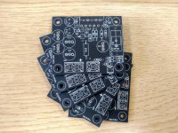
I've ordered 5 of 00940's layouts from JLCPCB, I'll build four of them & then see how close the DC offsets are & what lengths I need to go to in order to successfully parallel 2 of them. Thinking about this I now understand better why Crown Macrotechs used to have their TO-3 output devices colour coded or numbered in the factory, according to their tolerances, so that the amps supported parallel mono operation in addition to bridged mono. I've been looking through the thread on 00940's layout but I've not yet come across a list of recommended component values?
I'm assuming 'DC servo' is not referring to the same little servo motors I use in my model planes...?
I'm assuming 'DC servo' is not referring to the same little servo motors I use in my model planes...?
There's one on the (mis) Adventures in HiFi website that 00940 put together from MouserI've been looking through the thread on 00940's layout but I've not yet come across a list of recommended component values?
I'm assuming 'DC servo' is not referring to the same little servo motors I use in my model planes...?
That's a valid assumption. An image search for "DC servo amplifier" will give you some schematics. You may also find National Semiconductor (now TI) Application Note AN-1192 informative. They used the LF411 in the DC servo. It was great in its heyday, but something like the OPA277 would improve the DC performance considerably.
Tom
There's one on the (mis) Adventures in HiFi website that 00940 put together from Mouser
In this particular case, the last two resistors are the ones which have to be changed to their 0.1% version. A 1/2W rating at least.
Something like:
CMF5520K800BER6 Vishay / Dale | Mouser Belgique (no 22k1 in stock but this is close enough)
CMF551K0000BEEB Vishay / Dale | Mouser Belgique
The output resistors could be:
LVR05R2000FE73 Vishay / Dale | Mouser Belgique
Hi, I always read some of the problems people have in building projects, as it has been my business and hobby for over fifty years. I notice that you dismiss 'out of hand' lm3886 boards by kmtech, stating that you had to file the boards. I must say I'm surprised, I have built twenty or so of kmtechs split rail lm3886 boards, and PROVIDING the lm3886 is mounted correctly and not just soldered in they will fit. I have used dozens of these chips, all from extremely reputable suppliers, and in almost every case the chips connections are misplaced due to incorrect packing. I do think it a little un fair to dismiss someones products for this reason. I actually mount the ic to the heatsink, then the board, and then solder. As I said though, I've never had any ic thatr I haven't had to straighten or align some or all of the pins. You can get 'straighteners' for dil ics, but not offset ones.
regards john
regards john
Much of my reticence toward using the KMTech boards comes from the fact that the parallel board they sold me literally does not work without modification, as the mute components are simply not implemented. In a response to my question via eBay they explained that this was an older version of the board they'd sold me, where the mute components were left out for the user to implement themselves, either globally or per IC. However the fact that this wasn't mentioned anywhere in the listing, nor in the printed instructions, nor is there any support on the board (in terms of pads or thru holes) to actually add these components, makes it look a lot like they simply forgot them & don't want to own up to the mistake. I see the version of the board they're selling on eBay now is different & actually has a trace to pin 8 of each chip.
PCBs arrived from JLCPCB, components from Mouser should get here on Monday. The aforementioned BOM is missing the SMD resistor R8 for the bottom of the board, so I ordered these which I'm pretty sure are the correct size;
CRCW120622K0FKEA Vishay / Dale | Mouser United Kingdom
CRCW120622K0FKEA Vishay / Dale | Mouser United Kingdom
Attachments
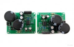
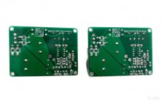
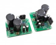
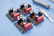
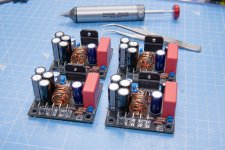
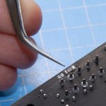
It's been a while, but I've finally made some progress. First time soldering SMD but it was pretty straightforward with a decent pair of curved titanium tweezers.
Just to double check, I'm fine to power the amps without a speaker attached in order to measure the DC offset, correct?
Just to double check, I'm fine to power the amps without a speaker attached in order to measure the DC offset, correct?
Attachments
- Status
- This old topic is closed. If you want to reopen this topic, contact a moderator using the "Report Post" button.
- Home
- Amplifiers
- Chip Amps
- 'Best' LM3886 PCBs (both single & parallel)