Hi Guys,, I've built a TDA2030 audio amplifier and I"m having problems with the Single supply circuit.
When I install C2 The 22uF cap in the Circuit it shuts the amplifier down.. I'm wondering what that Cap is for actually and why this happens.. When the Cap is removed the TDA2030 works.. I haven't tried different Cap values and the circuit is built to the schematic.. I'll try and post a gif of the schematic. Thank you. Terence.
When I install C2 The 22uF cap in the Circuit it shuts the amplifier down.. I'm wondering what that Cap is for actually and why this happens.. When the Cap is removed the TDA2030 works.. I haven't tried different Cap values and the circuit is built to the schematic.. I'll try and post a gif of the schematic. Thank you. Terence.
Attachments
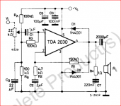
The 22uF cap and 4.7k resistor are there as a filter to limit the lower frequency bandwidth limit of the amplifier and to set the gain in concert with the 150k feedback resistor, with which the 4.7k resistor forms a voltage divider. Almost all conventional power amplifiers using negative feedback will have this form of divider/filter. You also see it as R4+C10+R3 in post #2 above. The filter generally has a -3dB frequency of less than 5Hz so there is little or no audible effect.
FWIW, the 2x1N4001 diodes are called flyback suppressors, catch or flying catch diodes - a safety feature, preventing spikes on the output caused by the inductive loudspeaker load, from causing damage to the amplifier. I would think they aren't considered necessary at the low voltages in a small audio system for cars. Here, it seems the designer is trying to add some insurance for the added risks of DIY. Maybe that was unwise if they didn't know exactly how the chip worked and what protections it already had.
FWIW, the 2x1N4001 diodes are called flyback suppressors, catch or flying catch diodes - a safety feature, preventing spikes on the output caused by the inductive loudspeaker load, from causing damage to the amplifier. I would think they aren't considered necessary at the low voltages in a small audio system for cars. Here, it seems the designer is trying to add some insurance for the added risks of DIY. Maybe that was unwise if they didn't know exactly how the chip worked and what protections it already had.
Last edited:
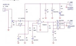
...Then it dawned on me that you might be talking about the 22uF cap from the midpoint of the 3 x 22k resistors at the input and ground (yes, we do need to be specific). If adding the cap kills the signal, it may be that it is charged and takes time to reach the midpoint potential of the input (pin 1), in which case you could measure the voltage there (without speaker connected) and then check what you hear after the voltage settles to about half the supply voltage.
Whilst the circuits appear to follow ST Micro's standard application notes, I would look at ST's original suggested schematic and check your assembly against it directly, only because its clearer about connections and easier for me at least, to follow.
Whilst the circuits appear to follow ST Micro's standard application notes, I would look at ST's original suggested schematic and check your assembly against it directly, only because its clearer about connections and easier for me at least, to follow.
Attachments
Hi W.O.T and Ian. Thank you for responding... I built the circuit to the Schematic that Ian posted.. and I was thinking that I mentioned the 22uF capacitor ( C2 ) in Parallel with the 100k(Rb) resistor, in some cases called Cb or C2. Sorry for the confusion Ian. At first I thought I had the Cap in backwards,, like I had the input Cap C1, but nope it was in correctly.. The circuit works great without the CB cap in it.. I'll keep horsing around with it. Thank you W.O.T. for posting the Schematic,, I've never seen that one before..
Hi Mooly,, No I didn't remove R3. It is 100k for the Schematic that I used. I always check and recheck components before I install them... One never knows what mistakes can happen either late and night or when working on something for waaaaaaaaay too long.. I've checked the voltages and I'll do some experimenting on the bread board with different Cap values, Thank you for your reply.
When I install C2 The 22uF cap in the Circuit it shuts the amplifier down.. I'm wondering what that Cap is for actually and why this happens.. When the Cap is removed the TDA2030 works.
Sounds like that capacitor is shorted, or in backwards. Its main function
is to filter the power supply noise. The amp will function with or without it.
Check the DC output voltage when the amp stops working. Does it saturate
to the rail, or ground?
Last edited:
Or it´s connected to the wrong end of R3, the 100k bias reference resistor,
in which case it *straight* shorts signal to ground.
Yes, if the capacitor is connected to the wrong node, anything could happen.
I'd like to know if the DC output voltage changes when the capacitor is in circuit.
Of course, it should not, but I bet it does.
Last edited:
Yup one problem Ray,, Bad cap,, I checked that thing about 10 times.. everything I tested it on said it was good.. Aaaaaarrgh!,,, So Changed the cap and found another problem.. Wrong Node. Eeeeek,, LOL Thank you for your help,,, Super appreciate it.
Breadboards can be a real problem. The silk screen normally on pcbs is a real help.
Hi JM,, Yes,, Cap connected to the wrong end or node as Ray would put it.. along with a bad cap,, Circuit works great,, I just have to increase the supply voltage up tor around 20 volts from 15volts,, Circuit is clipping slightly when input signal is over . 5 volts.. Thank you for your Help. ")
- Status
- This old topic is closed. If you want to reopen this topic, contact a moderator using the "Report Post" button.
- Home
- Amplifiers
- Chip Amps
- TDA2030 Single Supply Problem