The following is mostly the result of a desire to transition from Eagle to Kicad. The result of the desire to build a 8 channels amp too, an amp that I could use in various configuration for active speakers.
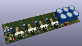
But 8 channels could easily turn into a big wiring mess. So I drew a kind of mother board for 4 lm3886 modules. The modules would be soldered vertically, through a 2*16 angled pin header. The board is 250mm*70mm as is. It would be very easy to slightly redraw it to switch the PS from side, to easily fit a pair into a big enclosure with heatsinks on the sides. With the modules 65mm long, it would fit into a 2U case (if heavy duty use isn't expected)
It incorporates a PS (with up to 6x 12000uf/35v caps), 4 independent dc offset protection circuits and 4 sharing resistors. I still need to add a common circuit for muting at turn-on/off. I'm also considering making the pcb a tad longer to incorporate a bridging circuit.
With a 2x20vac/250VA transformer giving 28v rails, one could either have 4 simple amps (38W/8r, 68W/4r), 2 simple amps + 1 BR100 (100W/8r) or even a single bpa200 (250W/4r).
Ideas or opinions on this ?
Attachments
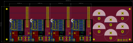
red is topside (component), blue is underside. For through-hole ground pour is normally topside (especially if the holes are not through-plated), so this board is reversed from convention (not an issue electronically though).
In general signal traces could be wider (this isn't exactly a crowded logic pcb!) - narrow traces are easier to break where they meet the pads, especially for through-hole.
In general signal traces could be wider (this isn't exactly a crowded logic pcb!) - narrow traces are easier to break where they meet the pads, especially for through-hole.
@Tom: good point on the connectors, no reasons to cook them.
@Mark: the tracks are 12mils wide as is. I'll bump them to 16 or 20 mils. You're right on top/bottom btw, I reproduced in Kicad the color scheme of Eagle (force of habit...).
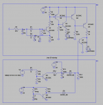
Here's the DC protection. I still have to put in the common muting part onboard (bottom box). D7 takes the place of the tlp3906, D9 is a fault indicator.
edit : to give credit, the DC protection is mostly coming from here: Loudspeaker Protection and Muting
@Mark: the tracks are 12mils wide as is. I'll bump them to 16 or 20 mils. You're right on top/bottom btw, I reproduced in Kicad the color scheme of Eagle (force of habit...).
Here's the DC protection. I still have to put in the common muting part onboard (bottom box). D7 takes the place of the tlp3906, D9 is a fault indicator.
edit : to give credit, the DC protection is mostly coming from here: Loudspeaker Protection and Muting
Attachments
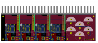
Moving to Kicad is surprisingly easy. Some frustrating experiences with the libraries setup and the system to move tracks around but that's pretty much it. The 3d viewer is actually useful to check how compact things can be. And its fun too ")
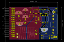
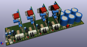
I'm still cleaning up the schematic/silkscreen but things go slowly forward. With a bridging adapter (just a dual opamp), the board is now 260*70mm. I dropped the turn-on delay for the relays as the lm3886 modules have a mute cap by default.
I'm still cleaning up the schematic/silkscreen but things go slowly forward. With a bridging adapter (just a dual opamp), the board is now 260*70mm. I dropped the turn-on delay for the relays as the lm3886 modules have a mute cap by default.
Attachments
- Status
- This old topic is closed. If you want to reopen this topic, contact a moderator using the "Report Post" button.
- Home
- Amplifiers
- Chip Amps
- Flexible backplane for 4 lm3886 amps