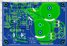
Made a board layout for the chip tda7294 in inverted switching on (without electrolytic capacitor in the feedback).
It`s universal (SMD or through-hole ) soldering Board.
Your comments on the layout of the board. Quibbles, tips?
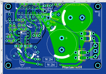
It`s universal (SMD or through-hole ) soldering Board.
Your comments on the layout of the board. Quibbles, tips?
Attachments
Some generic thoughts:
Ideally, when creating a layout for IC based PAMP, I would recommend to start from power supply section and try to locate bypass capacitors as close as possible to IC pins. First start with small 100nF capacitor to the larger ones. In some case, when you want to go even further you can put a snubber network somewhere close to the IC, too.
The next thing is to try and place the board connectors (input, output, power supply) in such way that their tracks could go to IC pins in most straight-forward way. Avoid mixing input tracks with high current output or power supply tracks.
Then locate what should be the shortest path to bring output signal to NFB.
Consider using star-on-star layout grounding scheme. There are already discussions on that bit it seems that is the most usual/generic grounding scheme. It's not the best out there and it's not the only one.
Your concrete solution:
At quick glance it seems you have covered above topics in the PCB layout.
Are you sure that TDA7293/4 is appropriate IC for inverting configuration? What happens during the transition from operating to mute mode and vice versa?
A vital thing with the 7294 is the feedback resistor.
This path must be as short as possible or you will get oscillation on the output.
1mm = 1nH inductance and long tracks will cause havoc.
Also with 7294 don't change the gain.
It has a minimum gain before oscillation starts.
I got caught out with a valve/7294 circuit where I needed less gain due to the valves gain. The oscillation radiated nicely back to the valve and I simply had a oscillator !
I managed to kill the oscillation with a 1000pf across + and - inputs on 7294.
Quibbles, tips?
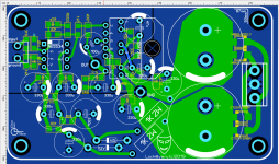
To reduce noise, the power take-off points for the RC decouplers should be direct
from the capacitor terminals, not from near the rectifiers. I'd delete both land areas
and use wide, direct traces for all the diode/cap/decoupler connections.
Last edited:
1. Mutе does not work in inverted mode.
2. the feedback resistor is made of two because the noise of a large nominal resistor is greater than the sum of the noises of two small nominal. And as for me, the resistors are very close to TDA7294. No?
3. The gain is selected based on the results of normal (without generation) operation of 4 pairs of chips tda7294.
4. Remove the solid fill of the earth can be, but it will be worse (by measurements), in bad variants of wiring helped the connection of the power ground and the signal ground by resistor 1-3 ohms. But in this case, it is not needed, it is worse
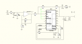
scheme:
I wouldn't have used two feedback resistors as this makes feedback path longer. It needs to be as short as possible.
- Status
- This old topic is closed. If you want to reopen this topic, contact a moderator using the "Report Post" button.
- Home
- Amplifiers
- Chip Amps
- TDA7294 ideal board layout