Can u post a picture of the chip?
I have an image of a real vs. fake TDA2040 die but looks like I have to externally link images. Not sure if I have the 1875 chip anymore, but I do have die size measurements:
Authentic LM1875 3.7 x 2.7mm, 10 mm^2
Authentic TDA2040 3.2 x 2.6mm, 8.3 mm^2
Counterfiet TDA2040 2.2 x 1.8mm, 4mm^2
Note the tiny die area of the faked part. When I test the current limit by short circuiting the output, the authentic parts protect themselves while most of the fakes immediate fail.
Yes, I also changed most of the other stuff (besides the X7R-Caps), but I think it's more or less more a mental than an audible upgrade.
Here in Germany I pay around 1,70€ which is roundabout 1,92$ for the little "China Blue"-Kit. I think at this Price one cannot expect more Bang for the Buck.
The Amp works with the standard Components pretty well and that was, as I tried one of these for the 1st time, more than I expected.
The best one can do for the little Amp is to give it some 1000µF Electrolytics in the PSU, because this will give a real & immediately audible Improvement in Dynamics and Punch.
Yes, I also used the components that come in the kit except the power capacitors that change to original Nichicon KW (470uF/35v).
Once I have clear my final configuration I´ll begin to change resistors and the rest of capacitors but for me, the most surprising thing is that for $ 2 you have an amplifier that works and sounds perfectly.
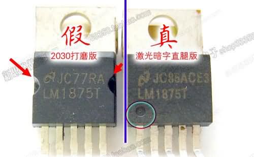
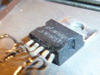
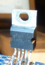
Ordering the PCB would cost us much more!The LM1875 that come in my Kit have some "endidures" on the sides, which has made me suspect and think that they are actually TDA2030. Something like this:
Could someone tell me the temperature reached by the LM1875 connected to speakers please?
Interesting.. I have 4 of these 2$ kits.
But also have all Mouser sourced bits to build the Data sheet Amp circuit.
Not willing to expend any effort on suspect bits.
Money is Much easier to come by than life hours. Even those spent 'testing' chips
I initially thought of using the Kit PCB's (why I bought them)... but frankly perf board or a point to point build gives an IMO potentially better layout.
The LM 1875 chip IS the amp.. rest is just minor add ons
But also have all Mouser sourced bits to build the Data sheet Amp circuit.
Not willing to expend any effort on suspect bits.
Money is Much easier to come by than life hours. Even those spent 'testing' chips
I initially thought of using the Kit PCB's (why I bought them)... but frankly perf board or a point to point build gives an IMO potentially better layout.
The LM 1875 chip IS the amp
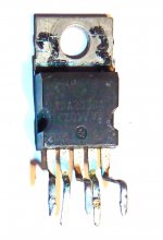
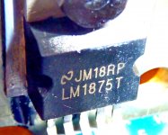
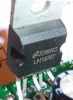
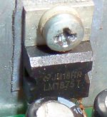
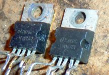
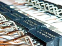
.. rest is just minor add onsSome Pictures. 1st is a TDA2030, the Rest different LM1875 I found on my HDD. No Pics from the Net, all by me, and I think they're all original LM1875, because to fake these things is economically absolute Nonsense.
The Chinese just buy totally huge amounts of the parts needed, and so they can sell an Amp for 2€/$.
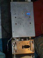
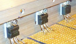
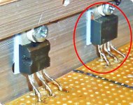
The last is the Backplate of one of my active Loudspeakers (that was all I had, the alternative had even more holes in it). It's 250 x 170 x 3 mm Aluminium, and on the inside I mount three LM1875. After Hours of pretty loud listening (with +/- about 27V) to Music that has to be played loud, the Plate is warm. If not oscilating to Death and mounted with a tiny amount of thermal Paste the 1875 does not produce any Heat worth typing about.
The Chinese just buy totally huge amounts of the parts needed, and so they can sell an Amp for 2€/$.
The last is the Backplate of one of my active Loudspeakers (that was all I had, the alternative had even more holes in it). It's 250 x 170 x 3 mm Aluminium, and on the inside I mount three LM1875. After Hours of pretty loud listening (with +/- about 27V) to Music that has to be played loud, the Plate is warm. If not oscilating to Death and mounted with a tiny amount of thermal Paste the 1875 does not produce any Heat worth typing about.
Attachments
-
 000-20190810-184620.jpg184.7 KB · Views: 438
 -
 008-20190801-053536.JPG520.6 KB · Views: 137
 -
 007-20190425-061150.JPG344.8 KB · Views: 141
 -
 006-20190331-051426.JPG361.3 KB · Views: 136
 -
 005-20190323-220310.JPG333.6 KB · Views: 160
 -
 004-20181007-235821.JPG499.2 KB · Views: 164
 -
 003-20190810-183951.jpg386.7 KB · Views: 399
 -
 002-20190810-184438.jpg379.7 KB · Views: 405
 -
 001-20190810-184620.jpg460.1 KB · Views: 485
The LM 1875 chip IS the amp
... and even without Music it's nearly Art
>Attachments
... After Hours of pretty loud listening (with +/- about 27V) to Music that has to be played loud, the Plate is warm. If not oscilating to Death and mounted with a tiny amount of thermal Paste the 1875 does not produce any Heat worth typing about.
Thanks !!!
I question the authenticity of those ICs. I've been buying Texas instruments / National Semiconductor parts for a while and they never have the semi circle indentations on the sides nor the bevel along the top of the encapsulation of TO-220 parts (the ones I've gotten anyway). Go to the TI forum on their site and ask them. They will likely tell you that these are counterfeit parts.
Sure they may work but they will not reach the rated power of an authentic part, less reliability due to the smaller die size and may lack circuit protections and won't deliver as low as distortion.
Sure they may work but they will not reach the rated power of an authentic part, less reliability due to the smaller die size and may lack circuit protections and won't deliver as low as distortion.
Last edited:
You are talking about the right one. I noticed the different cases, too. As far as I imagine could the right Version be the older Production, while the newer Ones look like the one on the left. Both Versions take +/- 27V and sound great without getting hot.
Attachments
think they're all original LM1875, because to fake these things is economically absolute Nonsense.
The Chinese just buy totally huge amounts of the parts needed, and so they can sell an Amp for 2€/$.
That's perhaps a bit Myopic
Our Eastern friends have been found to fake Resistors.. a fractional cent part.
Most of the costs of a Chip is in the Fab Machines AND the Die design.
Fab machines have history of being run 'overnight' for clandestine production runs.
Then when one simply copies (steals) a Die design... then deletes portions of that die copy ..even lower mfg costs result.
We then start getting Alleged ~3$ chips being fitted to "amp" kits that free ship for 2$ all in. Genuine parts ...Really?
Wanna buy a Bridge?
The Real problem isn't (for me at least.. dunno about Texas Instruments tho) xerox type Copies.. it's the very badly made imposters.
No need for the Sillyscope testings..Just dead short the things.Yesterday I received some original LM1875T (€ 3.31 per unit in Mouser) and they have no endidures.
I'm going to set up a second amp with them and I´ll try to do some tests to see if my oscilloscope can catch differences.
Genuine will self preserve/survive, Fakes will die... instantly.
Quick and dirty clean power measurement into 8ohm resistors gives me 18W/ch from the +/-27Vdc power rails before clipping. I set the volume at max and measured the voltage across the load when adjusting the preamp volume (12Vrms). Seems to be about right according to the spec sheet for the chip.
Does this chip have a maximum signal input voltage and should I measure any preamp signal to ensure it is below this value?
If I use a preamp for volume control, does this integrated amp act like a power amp when volume is at max (~zero resistance in the pot)?
Is there any issue with leaving this amp at maximum volume when driving it with a preamp in this setup? If there is none, does anyone include a volume pot bypass switch in their builds?
Thanks
Last edited:
Quick and dirty clean power measurement into 8ohm resistors gives me 18W/ch from the +/-27Vdc power rails before clipping. I set the volume at max and measured the voltage across the load when adjusting the preamp volume (12Vrms). Seems to be about right according to the spec sheet for the chip.
acc. to the datsheet figure 5 - you should get at 27V rail into 8R about 25watt at THD 1% so unclipped (you will see this on scope) 18W looks not bad. figure 9 show you that you heat dissapation is really high = 32Watt
Does this chip have a maximum signal input voltage and should I measure any preamp signal to ensure it is below this value?
hmm... i am not the expert but at page 2 there are the max ratings and here is written that its possible -Vee to VCC so nearly your rail voltage !
If I use a preamp for volume control, does this integrated amp act like a power amp when volume is at max (~zero resistance in the pot)?
in my opinion yes - if the wiper is correct set and do a 0R
Is there any issue with leaving this amp at maximum volume when driving it with a preamp in this setup? If there is none, does anyone include a volume pot bypass switch in their builds?
souhld be ok...but be aware of some popon/po off of your amp !.....sorry but i don not use a pre amp - directly from my DAC´s to the amps
Thanks
my comments in bold
chris
Thanks for the feedback Chris.
I will also just be using it with a DAP but some can have quite low output voltage (iPhone is quite low, but I will be using Benjie S5 or M6, or AP80)
I just read that the power amp volume setting could set to the level that gives lowest noise floor when listening at the speaker.
Maybe: set and leave the DAP volume to a level that does not cause clipping in the preamp (when it is turned to max volume), then leave power amp near max volume. This might give good performance and allow the preamp to safely control volume with no chance of clipping?
I guess I can measure preamp (NE5532) clipping versus Signal input voltage as well. I guess this would be a scientific approach to get clean power levels. I guess that clean power measurements do not necessarily indicate S/R.
I know there is lots of discussion on this online (eg typically you want to be 1/2 to 2/3 output on your pre-amp at your normal listening level)
Last edited:
I don’t think the preamp is clipping when the source is the ipad min at max volume because: with the amp at low volume I can see clipping starting when the preamp is at @95% volume. I don’t get near this level during these tests. The preamp is supplied by a 15Vdc regulated supply. I cannot drive the amp to clipping without the preamp, the source voltage is too weak.
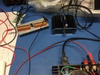
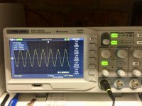
Here is a couple of pictures of my setup.
This time when I am pretty sure the preamp is not clipping:
> The load is measured as 8.15 ohms
> The supply rails sag to +/- 25.5Vdc just before clipping as measured at the amp power supply connection on the board. (I only had the load on one channel)
> The Vrms measured across the load with the DSO just before clipping is 13.6V
That gives me 22.7 W/ch in my build.
Do I have a measurement, calculation or build issue?
Attachments
I'd say it's right. According to the spec sheet for LM1875 is 25W @ +-25vDC @ 1% THD. You're not far off it. Are you measuring supply voltage at the IC itself? Perhaps there are some losses in the wiring and board itself.
No, just at the power terminals.
I wonder if the power resisters change value significantly when hot!
From the spec sheet I also notice that for 8ohm loads, THD is lowest just before clipping. Does this indicate that best perfromnace is when the amp is operating just before clipping at about 20 watts?
Last edited:
- Home
- Amplifiers
- Chip Amps
- LM1875 Amp layout