Not sure what the layout is on top... But it looks maybe like the fuse output is near the opposite rail of the transformer?Where is particular can you a potential short?
Alright, ditching the magnetic shielding idea
RCAs moved over.
Do I put the volume pot before or after the preamp?
Do I only use shielded cable for the wiring between the signal input and the main amplifier board input?
Not sure why in first posts I'd be in such a hurry to ditch the copper... it'll make nice shield for the amplifier.... particularly covering input circuits...
One vote for, one against copper shield around toroid ?
Toroid is low emission but it is quite close to the amplifier. Would a shield be needed? I guess I’ll have to see when it is running.
A problem I do have is earthing the chassis for electrical safety. There is no continuity between any panel even though they are screwed together. I have somestainless star washer but nit sure how to make an effective ground.
One vote for, one against copper shield around toroid ?
Toroid is low emission but it is quite close to the amplifier. Would a shield be needed? I guess I’ll have to see when it is running.
A problem I do have is earthing the chassis for electrical safety. There is no continuity between any panel even though they are screwed together. I have somestainless star washer but nit sure how to make an effective ground.
Anodised aluminium has indeed a sheet if insulation on it - namely the anodising!!
If you tighten a screw and undo it a few times you should find they eventually connect . Do this in all screws to be safe.
Also note to test all panels with continuity probe unless you have exposed areas you will have to scratch a little anodising off. Do this on the inside out of view!
Last edited:
OK thats cool. But the insulated windings and rubber mats are irrelevant. Anything connected to your chassis base then coming in contact with the top of the bolt competes a circuit through the core = shorted turn. Just letting you know of the pitfall!
How did you get on with earthing?
The proper safe way is to have a dedicated bolt to which your mains earth connection is made. you can use antishake or split washers to prevent it all undoing and an added safety feature is to use 2 nuts tighten one down onto your assembley then another one on top of it.
Are you also now getting the various chassis pieces to connect ?
Last edited:
Hi, thanks for the advice blue-glo.
I had not come across the particular issue with the transformer centre bolt. I think I understand now.
Have not done any more assembly yet.
I will have to solve the safety earth issue before I complete the fixing of the other 3 PCBs and transformer. A stainless steel star washer certainly chews through the anodising in the recessed holes that take the chassis assembly screws and I was able to get continuity between one screw and the mounting bolt that secures the amp angle bracket to the heatsink. I will drill and tap a hole for a 3mm bolt near the IEC power connector. Your advice on the earth bolt is consistent with what I have read - thanks for that. Maybe it won’t be that difficult.
I will keep posting build updates. Really appreciate the forum members taking an interest and providing advice. My only previous experience was building a 12v TDA7297 stereo amp in a wooden enclosure. This new build is a step up! Hope it works as it certainly is not a cheap exercise.
Last edited:

Just tried EasyEDA, it is either not intuitive, or I have no intuitionHeadache.
Just stumbled upon the web version of EasyEDA. The app on my iPad was not a good introduction - it sucked. Looks like I could have found the components I needed using the webpage versions library.
I will give it a go another day.
Last edited:
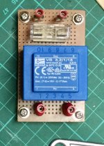
Nice. I do think with the effort you've put into the rest of the build, a proper PCB for the small transformer will be a nice touch [emoji106] and will be stronger than a perf boardJust stumbled upon the web version of EasyEDA. The app on my iPad was not a good introduction - it sucked. Looks like I could have found the components I needed using the webpage versions library.
I will give it ago another day.
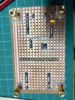
I coated the veroboard with PCB lacquer to prevent any corrosion, and left it as is.
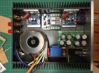
Well, it is a very tight fit. I was too cute with the case size - lesson learnt! There will be some difficult fitting the wires (I think I put the speaker protection board in the worst orientation possible) but I can run most under the boards.
Next: fit the safety earth bolt, ensure all chassis panels are earthed, remove and bench test each module, reassemble and complete the wiring, test.
I have one issue with the supplied knob and the “Alps” pot. The pot rod has a waisted area right where the knob grub screw goes. Tightening it securely pulls the knob over? Guess I will have to tap another hole, if I can get a tap that small, that is one tiny grub screw maybe only 1mm or less!
Attachments
Why not file a flat in the shaft where the screw needs to go?Going to use a different pot. I bought the wrong one
It is a ribbed shaft, bought the wrong one. Easy fix.
Just a few more queries before I start the final test and assembly in a couple of weeks.
I will put a 10nf 300v Kemet X1 cap across the mains switch to eliminate any on/off noise, even though I don’t know if it is necessary,
What are the pros and cons for adding the 3.5mm jack to the front vs rear panel? Are ther any nice surface mount ones available? I have gold coloured ones with knurled nut that would be seen from the outside.
My fuse choices are (I presume they are all necessary):
3A slow for mains
2.5A fast between toroid 18vAC and rectifier board
2.5A fast 18vDC to amplifiers
250mA fast between 18vAC transformer and the circuit protection PCB (guessing this one at the moment as no current details provided by seller, but I can test draw on bench)
Do I need to test DC offset at the speaker outputs? There is no bias adjustment (all taken care of in the IC I am told).
I had to turn the IEC socket over (fuse holder at bottom), is this illegal?
I am not going to use an inrush current limiting NTC thermister before the toroid.
I will secure all connections and stabilize the big caps with hot snot
Cheers
Duncan
- Home
- Amplifiers
- Chip Amps
- LM1875 Amp layout