That is way better IMO [emoji6] now your signal path is nice and clean.I suspect you may be right, especially since the chassis is completely metal and screwed together tightly.
Sure, for better heat distribution. I am going to keep uploading photos to keep track of setup.
Should I make a steel shield to isolate the transformer?
Could someone sketch in a mains earth and ground wiring layout? I am not sure if they are to be joined at the same point on the chassis.
I almost forgot that I have some inline or PCB fuse holders to install between the toroid and power board and maybe between power board and amplifier boards, not sure what is best practice.
Thanks
Attachments
Last edited:
Look forward to seeing the finished product!Thanks Bro
Should I make a steel shield to isolate the transformer?
Toroidal transformers hardly emit any field, unlike EI transformers. Just keep your audio path as far from it and the AC lines as possible, and you should be fine.
Twist any AC lines to reduce their emission and keep them close to the chassis.
Could someone sketch in a mains earth and ground wiring layout? I am not sure if they are to be joined at the same point on the chassis.
Grounding is a much contended issue... here are my thoughts but others may have different suggestions") In the end, do what works for you.
In the end, do what works for you.
* Take mains earth to chassis as close to the inlet as practical. Make it very secure (crimp lug + soldered) as this is for safety.
* Run 0v or power ground independently to both channels from the transformer secondary (or power supply board if single rail). Keep it isolated from chassis ground. If you like, twist it with the DC supply.
* I generally prefer to leave audio ground floating - to sidestep ground loops in the system - but if you feel that is unsafe (and it does have potential to be in certain circumstances), then ground it securely to the chassis at the inputs, not to the same point as the mains ground.
* Take the audio ground from there to the volume control and from the volume control to the amplifiers, using shielded cable.
* I am not sure what potential the chips' bodies are at but you will almost certainly want to isolate them from the heatsink with a mica washer or similar regardless.
Toroidal transformers hardly emit any field, unlike EI transformers. Just keep your audio path as far from it and the AC lines as possible, and you should be fine.
Twist any AC lines to reduce their emission and keep them close to the chassis.
Could someone sketch in a mains earth and ground wiring layout? I am not sure if they are to be joined at the same point on the chassis.
Grounding is a much contended issue... here are my thoughts but others may have different suggestions
In the end, do what works for you.* Take mains earth to chassis as close to the inlet as practical. Make it very secure (crimp lug + soldered) as this is for safety.
* Run 0v or power ground independently to both channels from the transformer secondary (or power supply board if single rail). Keep it isolated from chassis ground. If you like, twist it with the DC supply.
* I generally prefer to leave audio ground floating - to sidestep ground loops in the system - but if you feel that is unsafe (and it does have potential to be in certain circumstances), then ground it securely to the chassis at the inputs, not to the same point as the mains ground.
* Take the audio ground from there to the volume control and from the volume control to the amplifiers, using shielded cable.
* I am not sure what potential the chips' bodies are at but you will almost certainly want to isolate them from the heatsink with a mica washer or similar regardless.
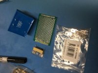
I have started sketching out the wiring but have got stuck with wiring and mounting of the separate 18v encapsulated transformer for the speaker protection board.
VB 3,2/1/18 | 18V ac 1 Output Through Hole PCB Transformer, 3.2VA | RS Components
I was going to put it on a double sided PCB with spade connectors, and a fuse on the 18v side. Then got worried about arcing across the tracks in the 240v end. Tried creating space by removing some tracks but I don’t like the outcome.
Not keen on just gluing it upside down to chassis floor.
Suggestions please.
Attachments
Last edited:
IMO if you want to do it right... Get a PCB made
Not too hard to design one on EasyEDA and get it manufactured at jlbpcb. There are likely the footprints you need already, otherwise making them isn't too hard. The software is free to use and the PCB manufacture is very reasonable.
There's other software and vendors too but I've used these and they did a nice job, also pretty fast.
I'm making a similar amplifier with the same LM1875 boards. Currently, only the chassis is connected to the power ground. My speaker posts and RCA input sockets are only connected to the star ground on the PCB board. (ie the PCB, speaker posts and RCA inputs are NOT connected to the power ground). Is that what you would call a floating audio ground?I generally prefer to leave audio ground floating - to sidestep ground loops in the system - but if you feel that is unsafe (and it does have potential to be in certain circumstances), then ground it securely to the chassis at the inputs, not to the same point as the mains ground.
* Take the audio ground from there to the volume control and from the volume control to the amplifiers, using shielded cable.
By having some components not connected to the power ground, is that an example of a potential safety issue?
By having some components not connected to the power ground, is that an example of a potential safety issue?
As I understand it, the risk of leaving the electronics floating is that if, somehow, the audio chain were to become "live" (due to a loose wire or a faulty transformer for example) - no fuse will blow, as it might were there a low impedance path to mains earth. This could expose the user to electrocution by touching audio cables or controls, for example.
Thanks for the fast reply. Just doing some more checking on this and can see it is a regularly discussed topic. Following a build in another thread, I had previously tried to connect all of the input and speaker negatives together, and then connected that to the power ground, but ended up with hum problems. Whereas, it is working fine, now. I've got enough clearance between the live A/C wires and the speaker and RCA components so that its not really feasible for them to connect. But still technically possible. I need to do some more reading.
It's one of those things, arguments to be made both ways.
Having said that, provided you ground the audio gnd/power gnd in one place and one place only (in the system), it shouldn't create a loop (and therefore, hum). The problem usually arises when you get multiple paths to and between grounds.
Having said that, provided you ground the audio gnd/power gnd in one place and one place only (in the system), it shouldn't create a loop (and therefore, hum). The problem usually arises when you get multiple paths to and between grounds.
IMO if you want to do it right... Get a PCB made
Not too hard to design one on EasyEDA and get it manufactured at jlbpcb. There are likely the footprints you need already, otherwise making them isn't too hard. The software is free to use and the PCB manufacture is very reasonable.
There's other software and vendors too but I've used these and they did a nice job, also pretty fast.
Just tried EasyEDA, it is either not intuitive, or I have no intuition
Headache.Oh dear [emoji6] well, you could always do it the old fashioned way with a marker pen and some etching solution ¯\_(ツ)_/¯Just tried EasyEDA, it is either not intuitive, or I have no intuition
Just tried EasyEDA, it is either not intuitive, or I have no intuition
Dip trace is free and ok to use.
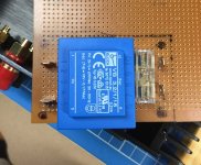
Thanks for the suggestions. Found some single sided veroboard in my first electronics toolbox from years back, so am going old school. Easier to remove the traces than on the double sided board with vias. I will remove a whole track or two to separate the high and low voltage sides. Output fuse. Input is fused at the power switch. Might have to strengthen the corners with solder where the mounting bolts will go - is that the best idea? The 3.2VA transformer is quite heavy.
Attachments
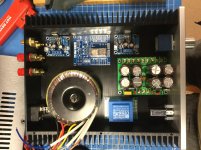
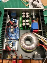
I’ll keep uploading build images for comment as I go, and for other people considering a similar project. Please let me know if anything looks dodgy.
LM1875 boards bolted to 4mm angle that is bolted to the chassis heatsink with heatsink compound between surfaces. I replaced the tiny 10uf electrolytic signal input capacitor with a film type, but look at the crazy size if it!
I broke a pin on one of the speaker protection relays so am waiting for replacement (the relays in this kit are recycled) before I can complete the board.
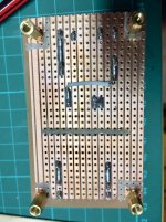
I mounted the small encapsulated transformer for the speaker protection board to a piece of veroboard and included a fuse holder on the 18v side. I used a Dremel with a small stone to remove some tracks.
It is going to be a squeeze fitting it all in but I think it will go. If I have to eventually fit a preamp board because the mp3 player signal is too low, that will have to lay on top of something in the low current side.
Can anyone see any problems at this stage?
LM1875 boards bolted to 4mm angle that is bolted to the chassis heatsink with heatsink compound between surfaces. I replaced the tiny 10uf electrolytic signal input capacitor with a film type, but look at the crazy size if it!
I broke a pin on one of the speaker protection relays so am waiting for replacement (the relays in this kit are recycled) before I can complete the board.
I mounted the small encapsulated transformer for the speaker protection board to a piece of veroboard and included a fuse holder on the 18v side. I used a Dremel with a small stone to remove some tracks.
It is going to be a squeeze fitting it all in but I think it will go. If I have to eventually fit a preamp board because the mp3 player signal is too low, that will have to lay on top of something in the low current side.
Can anyone see any problems at this stage?
Attachments
- Home
- Amplifiers
- Chip Amps
- LM1875 Amp layout