Looking at all the projects on this website, it somewhat seems strange to me that noone came up with a backplane that could accommodate a pair of amplifier modules while simplifying wiring and so on.
Let's imagine a 200*300mm pcb. At a first sight, we could have the following onboard:
- the main power supply,
- some auxiliary supplies (+/-15v, 5v),
- source selection,
- volume control, with a remote control option,
- an Arduino as optional control center,
- DC offset protection and muting.
And still have place for two removable amplifier modules (70*70mm), two input modules (50*100mm) and one preamp/buffer module (60*60mm). The input modules could be bal to se converters, DACs, phono preamps or even a raspberry pi.
Add two transformers, a big heatsink and some connectors and this would easily fit into a 350mm deep Slimline 2u hifi2000 case.
I confess that a big part of the attraction of this project is a personal itch to learn to use Kicad. But wouldn't this be worth trying ?
it somewhat seems strange to me that noone came up with a backplane that
could accommodate a pair of amplifier modules while simplifying wiring and so on.
Some commercial equipment is built this way, even Constellation. It does require
a higher level of systems engineering than is present in many DIY projects.
Last edited:
Indeed. Such a project would require a lot of attention to practical details.
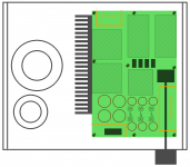
Here's a rough draft of what it could look like. Not a high power amp, something with rails at about +/-30V, lm3886, symasym, p3a or the like.
A not so trivial question would be what to pick as connectors for the power connections to the amp modules. Common headers strip are at best rated for 2A per pin. That's a lot of pins to get something beefy enough.
Samtec has some nice strong connectors. The pss-fws serie is rated for 11A per pin, the hpf-hpm for 13A. Not cheap though.
Attachments
This is something I've thought about for a long time too.
It would be good to be able to swap modules in and out easily to be able to compare or upgrade more simply.
The problem I've found is that the project PCBs all tend to be different dimensions and have different in/out placements. If I knew how to use Eagle and the like, I'd convert some of the existing layouts to a standard size -it would be good to have 'modular' versions of some of the fantastic designs presented here.
As for the higher power connections, perhaps just power screw terminals would suffice to allow making up power leads with ring terminals to keep things simple?
Anyway, I'm definitely interested in this too!
As for the higher power connections, perhaps just power screw terminals would suffice
to allow making up power leads with ring terminals to keep things simple?
These are quite good, made in versions up to 30A, and are surely the cheapest way to go.
Use boards with 2 oz copper and traces on both sides for max current.
Screw Terminals, PCB Screw Terminals: Keystone Electronics
Last edited:
Samtec has some nice strong connectors.
Would need a mixed signal connector like: https://www.samtec.com/connectors/rugged-power/signal-power
I didn't think about those screw connectors. Something like this one would do great, simply mated to plated holes in the pcb. Thanks for the tip.
I don't think mixed signal connectors would really be necessary. You could use these for power and common header strips for input signal.
@avtech23: yes, one couldn't simply reuse existing pcb. You'd have to design your own. Changing amps would also mean tapping new holes in the heatsink... As you'd be stuck with a particular in/out placement of the connectors, best consider options twice or thrice.
If only one size did fit all, but in audio that's so far from the case. Standardizing pcb connectors is a more fruitful approach I think. Amp modules need power, line input, output and perhaps protection/status connectors, and if those were all standard it would make it much easier to plug and play, without constraining sizes or shapes of module.
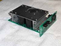
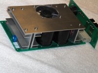
I did a design of Elvee's Circlophone.
I designed the board around the DIN standard 100x160 mm dimensions and a backplane to fit the standardized 3U high 19" rack unit (IEC 297 standard).
You could easily fit 8x50Wat amplifiers with the power supply into this 19" chassis.
The nice thing is you can get proto-boards the right size with fitting pads for the back-plane connector.
Picture attached.E
Attachments
@ mickeymoose : that's a very compact implementation, nice.
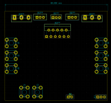
I started fooling around in Kicad. Here's a possible implementation of the amp module. It's 80*70mm. Transistors/lm3886 footprints are there to give an idea of the available space. Quite a few simple designs would fit.
Power would come either from left or right connectors (or both) depending on layout. Simple pin headers would provide input and aux power if needed. A concern with the screw terminals is insulation. Some solution would have to be found to prevent accccidental shorts.
Attachments
- Status
- This old topic is closed. If you want to reopen this topic, contact a moderator using the "Report Post" button.
- Home
- Amplifiers
- Chip Amps
- Modular backplane for integrated amplifiers ?