Hi folks.
I'm looking for some clarification and maybe an advice about PGA/VGA circuit.
I want to build rather simple circuit with 2-3 option to control gain over one stage.
So let's assume that there will be Gain=1 then 2 and 4 (if 3 steps) or just 1 and 2 (if 2 steps).
Basic schematic will look like this :
http://www.ecircuitcenter.com/Circuits/op_PGA/image002.gif
My question is - what type of IC or elements should I use to build this right?
CD4066 (or similiar), JFETs? Logic mosfets? Ultra small relay? SPDT switch as a IC package like MAX4649?
There is plenty of solutions all over internet and I'm totally unsure which one is the proper or safe one.
Thank you for your time and help
The problem with 4066 is that you need to drive each switch by yourself, and isn't capable of manipulate voltages below 0V unless you use single supply and the circuit is biased Vcc/2.
It is preferable to use HCF4051/52/53 series that have split supplies capability and you can do it with split supply in the audio path and still have usual +5V or +12V logic, the conversion is done internally. Also, a simple BCD or binary can control the attenuation easily.
It is preferable to use HCF4051/52/53 series that have split supplies capability and you can do it with split supply in the audio path and still have usual +5V or +12V logic, the conversion is done internally. Also, a simple BCD or binary can control the attenuation easily.
How about discrete parts like logic-mosfet or simple jfet?
Adding two-step gain stage will require one jfet/mosfet for switching am I right?
More step will require more parts or IC to save space and costs.
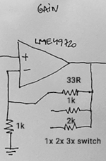
Here's picture of what I'm thinking :
https://i.stack.imgur.com/ZKnN8.png
I assume that RDS-ON will be important matter, so I should look for lowest possible?
https://www.electronicdesign.com/sites/electronicdesign.com/files/uploads/2015/12/ifd2628promo.jpg
Last edited:
I've used the LTC6912-2 programmable gain dual amp in the past, has all the resistor networks and analog switches built in for gains of 1,2,4,8,16,32,64. I had it after a low-noise microphone front end before I2S ADC. The -1 version has 1,2,5,10,20,50,100 gain settings.
One downside is that its SPI controlled, requiring a µController.
One downside is that its SPI controlled, requiring a µController.
I'm familiar with something like that but I just want to avoid any MCU in my design.
I'm rather looking for simple solution like SPDT switches or something build arround JFET/logic mosfets.
But I'm not familiar with those and I'm trying to gain information about advantages etc.
I'm rather looking for simple solution like SPDT switches or something build arround JFET/logic mosfets.
But I'm not familiar with those and I'm trying to gain information about advantages etc.
CD4053. 4-in multiplexer (switch). Particular advantage is that you can run the analog on +/-7V (DC-coupled ground referenced) and run the Control pins on +5V/0V (common logic levels).
Yes, the 4066 with mechanical control switches can be run all +/-7V. But the multiplexer implements what you want, less wiring.
Yes, the 4066 with mechanical control switches can be run all +/-7V. But the multiplexer implements what you want, less wiring.
I'm familiar with something like that but I just want to avoid any MCU in my design.
A simple solution which doesn't need an MCU is AD603 - its a DC voltage controlled variable gain amp with a range of about 40dB. It does have rather a lot of gain though when the volume's up to maximum so you need to attenuate the signal at the input. I use a transformer for this but you could equally use a suitable resistor. AD603 is very cheap on Taobao, under $1 and an 8pin device so not too much to connect to.
Yes, that's plausible, but being an RF chip it has some annoying defficiencies like low PSRR and the high gain issue (attenuating with resistors adds noise, not attenuating loses input headroom - and the THD is only so-so.
Another option might be a multiplying DAC with parallel inputs - hook the inputs to multiway selector switch for powers of two gain settings...
Another option might be a multiplying DAC with parallel inputs - hook the inputs to multiway selector switch for powers of two gain settings...
A simple .... AD603 ....
...a multiplying DAC ...
Did you look at mikolaj612's (externally hosted) image? It calls for just four switches, and is probably intended for just four gains. The AD603 seems like over-kill. The DAC may violate the wish for no MCU (true, powers-of-2 are possible).
Attachments
whenever I need some electronic switch in the audio path I choose an AC switch based on 2x 2N7002 with common source and common gate.
These are available and very cheap and do not add any noise.
Switching glitches are small compared to integrated CMOS-switches and can be further attenuated by inserting some 10megOhm gate resistor.
Keep in mind you will need 2xMOS transistors for a SPST-switch and 4xMOS for a SPDT - there is definitely no free lunch!
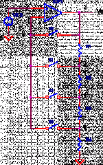
would this be a feasible simpler solution?
View attachment 784637
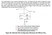
also check Analog Switches and Multiplexers Basics MT-088 TUTORIAL by Analog Devices, fig 28:

also check Analog Switches and Multiplexers Basics MT-088 TUTORIAL by Analog Devices, fig 28:
View attachment 784781
I exacly did that few months ago
In my opinion it's very good and easy to use solution.
Even when IC cost is kinda high it's worth it.
I exacly did that few months ago
In my opinion it's very good and easy to use solution.
Even when IC cost is kinda high it's worth it.
what IC or relay are you using?
what IC or relay are you using?
I picked ADG1413, but there is plenty of other switches (also from AD) that could do the magic
As far that I could tell I've got no issues with that IC and circuit.
I picked ADG1413, but there is plenty of other switches (also from AD) that could do the magic
As far that I could tell I've got no issues with that IC and circuit.
Cool, I got the ADG1611BRUZ the other day, should be OK unless I really need the break-before-make feature.

Its vital when switching negative feedback networks that there's always a path for the feedback, otherwise the output of the opamp will saturate to the rails producing speaker-destroying transients.
Thus the highest gain path should be permanently wired, and parallel resistors switched in to lower the gain. Even if your using fast analog switch chips its a really good practice, and with mechanically switching its essential.
Thus the highest gain path should be permanently wired, and parallel resistors switched in to lower the gain. Even if your using fast analog switch chips its a really good practice, and with mechanically switching its essential.
Its vital when switching negative feedback networks that there's always a path for the feedback, otherwise the output of the opamp will saturate to the rails producing speaker-destroying transients.
Thus the highest gain path should be permanently wired, and parallel resistors switched in to lower the gain. Even if your using fast analog switch chips its a really good practice, and with mechanically switching its essential.
thank you, will get the xx13 version then
- Status
- This old topic is closed. If you want to reopen this topic, contact a moderator using the "Report Post" button.
- Home
- Amplifiers
- Chip Amps
- Simple variable gain amplifier

