Hi.
First some clarification: I'm not a technician (but I can solder and even made my own circuits time ago) and where I live sending amplifiers to fix cost so much money, and headaches, that you end up with the dilemma of doing that or just buying a working used one, if not a new one.
So, both me and my brother have Edifier C200, some very nice sounding "hi-fi" computer speakers. His, stopped working. Slowly dying, in the suddenly cut the sound more and more frequently fashion, until it didn't output any sound. He opened the amplifier unit and found a dead cockroach, not stuck but lying around, but still there's the possibility it short circuited the unit until it stopped working (?). You'll see the photos...
So, as inflation started moving again I went and bought a TDA7379 for replacement before the price rises.
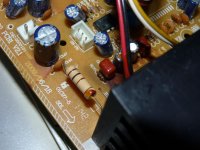
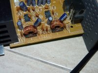
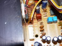
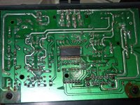
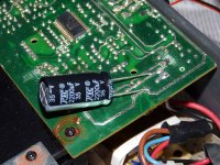
First some pictures. I had to severely lower the quality of some. Notice the brown coloration or brown substance around the amplifier chip and other components. Look at the close up of the amplifier chip legs. There's a capacitor of unknow value (and type, to me) near the chip, that looks damaged (my digital tester doesn't measure capacitors, sadly).
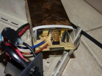
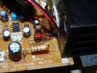
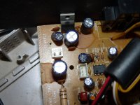
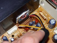
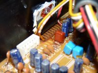
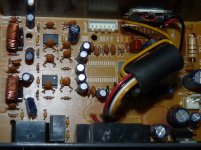
Sorry for the order.
So, what do you think? Does the chip look damaged?
By the way, this model has an anti distortion dsp chip somewhere (maybe in the front digital panel) that can cause problems too.
Sorry for my english and thanks in advance!
First some clarification: I'm not a technician (but I can solder and even made my own circuits time ago) and where I live sending amplifiers to fix cost so much money, and headaches, that you end up with the dilemma of doing that or just buying a working used one, if not a new one.
So, both me and my brother have Edifier C200, some very nice sounding "hi-fi" computer speakers. His, stopped working. Slowly dying, in the suddenly cut the sound more and more frequently fashion, until it didn't output any sound. He opened the amplifier unit and found a dead cockroach, not stuck but lying around, but still there's the possibility it short circuited the unit until it stopped working (?). You'll see the photos...
So, as inflation started moving again I went and bought a TDA7379 for replacement before the price rises.
First some pictures. I had to severely lower the quality of some. Notice the brown coloration or brown substance around the amplifier chip and other components. Look at the close up of the amplifier chip legs. There's a capacitor of unknow value (and type, to me) near the chip, that looks damaged (my digital tester doesn't measure capacitors, sadly).


Sorry for the order.
So, what do you think? Does the chip look damaged?
By the way, this model has an anti distortion dsp chip somewhere (maybe in the front digital panel) that can cause problems too.
Sorry for my english and thanks in advance!
Last edited:
So I just moved cables, dissasembly the digital pcb in the front (not in the pictures) and touched those components that looked burned to see if the legs were fine and it ocurred me to see if it turns on. So I connected everything and it turns on...Ok...what will it do now if I try to use it...And it works!!! Hahaha! No idea what happened of course but is working...with an important caveat! I recorded through my phone with Whatsapp a message to my brother with the amp still connected to it and the audio came with a ground sound added to it. Then I connected to my C200 and it didn't do it. And one very important thing I forgot to mention before: when we first tested this amp in my house it destroyed my sound card, but we also used his kind of destroyed cable.
So what could cause this bad ground effect in the phone!? I wanted to test the amp so if it works I could return it to my brother but now I'm scared it will destroy my actual equipment if I do!
Advise please!!
So what could cause this bad ground effect in the phone!? I wanted to test the amp so if it works I could return it to my brother but now I'm scared it will destroy my actual equipment if I do!
Advise please!!
Well, not even moderators listen to me!! haha
Ok, so, these amplifiers have 2 inputs "PC Input" and "Auxiliary Input".
The first one is RCA and according to specifications is "400mV +-50mV
The second is 3,5mm and "350mV +-50mV"
I assume both are 10kohms impedance.
http://www.biginformatica.tecnologia.ws/manuais/Edifier-C200.pdf
Now, while I record sound with my phone with the undamaged C200 "PC input" connected to it (not doing anything of course) sound is normal.
But with the "aux input" the sound camoes out with ground sound on it.
With the probably damaged C200 makes that effect but with both inputs.
This last amplifier destroyed a sound card. So, what could be the problem? How could I measure what could be malfunctioning (?) or different in that "PC input" of that amplifier compared to the PC input of the undamaged one?
And I'm going to try to clean the amplifier chip area, just in case humidity accumulated at some point there causing the original problem...
If the sound card got destroyed then some voltage must have got back into the sound card. Check for dc volts on input to amp. Maybe a capacitor has failed ?
Amplifiers can blow up for many reasons. Could be as simple as just driven too hard.
Maybe the speaker has gone low impedance and overloaded the amplifier ?
Amplifiers can blow up for many reasons. Could be as simple as just driven too hard.
Maybe the speaker has gone low impedance and overloaded the amplifier ?
If the sound card got destroyed then some voltage must have got back into the sound card. Check for dc volts on input to amp. Maybe a capacitor has failed ?
Amplifiers can blow up for many reasons. Could be as simple as just driven too hard.
Maybe the speaker has gone low impedance and overloaded the amplifier ?
Thanks for the answer. Some interesting points.
-"Voltage into the sound card". "Check for dc volts on input to amp."
Yes, first thing I thought about so what I did the other day was simply using the digital multimeter on the plugs connected to the amp, red on tips, black on ground. All 0 (most of the time at least). Did I do right or should I check that differently?
-"Maybe a capacitor has failed"
I searched for one but couldn't find one that looks weird, apart from that brown one near the amp chip. But it appears to be just stain form the brown stuff.
-"Could be as simple as just driven too hard."
Well my brother got it used, so who knows how the previous user...used it
-"Maybe the speaker has gone low impedance and overloaded the amplifier ?"
hmm how do I check for that? Using the multimeter on the speaker could be enough? At least I have my speakers, that are the exact same (should be) as reference...
But the amp, as I said before, is working now (maybe got dry in the amp chip legs? I will clean those surely today from the brown stuff), but I'm not trusting it will not kill another soundcard or motherboard or whatever it gets connected to it. I need to be sure it's safe.
Well, cleaned the area around and below the TDA7379 past saturday but then I reassembled it and again stopped working. Opened it again and it worked and stopped while I flexed the board... searched for broken paths, cold soldering....nothing. Re-checked capacitors, all seem fine. Now only works with a very low volume and without bass. At first started sounding like that and distorted and then without distortion, as if all bass died. Tried the headphones output, that is driven by a 5532 and works fine (so the DSP TDA7303 that's used to modify bass and treble and maybe something else is fine). Repaired some cables...nothing. Today changed the two 10uF 25v and one 12k 1/8w resistor in front of the TDA7379...nothing!!
And by the way it doesn't respond to flexing and tapping anymore!
Is it the 7379 dead? What else could it be?
And by the way it doesn't respond to flexing and tapping anymore!
Is it the 7379 dead? What else could it be?
Add some photos of the "cleaning" (scratching) and of the front panel PCB. This is the datasheet of that microcontroller https://www.datasheets360.com/pdf/-1067356977218892900
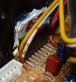
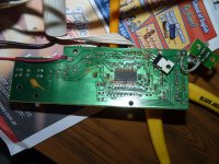
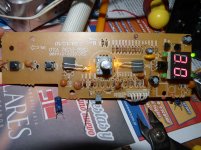
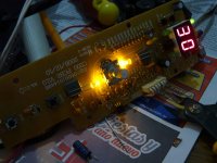
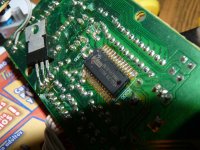
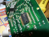
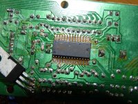


Last edited:
If flexing the pcb makes it fail then its either a bad soldered joint or a broken track or dodgy connector somewhere.
I had an amplifier pcb mess around and it turned out to be a hair line crack in a pcb trace. It was very hard to see.
On another amplifier it worked when I twisted the pcb and I had simply missed soldering a joint.
I had an amplifier pcb mess around and it turned out to be a hair line crack in a pcb trace. It was very hard to see.
On another amplifier it worked when I twisted the pcb and I had simply missed soldering a joint.
Now only works with a very low volume and without bass. At first started sounding like that and distorted and then without distortion, as if all bass died. Tried the headphones output, that is driven by a 5532 and works fine And by the way it doesn't respond to flexing and tapping anymore!
Is it the 7379 dead? What else could it be?
The fact that the headphones output is working means the signal chain upto that point is good. The TDA7379 is a fairly robust IC with extensive protections and simple circuitry, I am assuming its setup as a dual bridge amplifier, so before we assume the IC is defective could you do the following.
1. Check the output pins directly connect to the speaker (pin 1 and 2 to speaker 1), (pin 15 and 14 to speaker 2), you can do this step with the power off even.
2. Put power on and Check if the power supply to the IC is good using your mutimeter. Pin 13 and 3 should be the system positive voltage, while pin 8 and 9 should be ground potential (0 volts).
3. Check that the standby pin (Pin 7) voltage is greater than 1.5v
The brown residue is around the IC, which makes me suspicious if the IC could have encountered extreme heat which discoloured the board around it, or else a electrolytic capacitor nearby spilt its contents. The intermittent fault condition could be due to damaged PCB tracks or a faulty electrolytic capacitor.
Please do let us know the results of the tests. If everything else fails then replacing the TDA7379 might be considered as a last resort.
Last edited:
If flexing the pcb makes it fail then its either a bad soldered joint or a broken track or dodgy connector somewhere.
I had an amplifier pcb mess around and it turned out to be a hair line crack in a pcb trace. It was very hard to see.
On another amplifier it worked when I twisted the pcb and I had simply missed soldering a joint.
Yes I know but I spent a lot of time already searching for something and tested with the multimeter for bad connections and nothing! And not only that, but it stopped doing that, so something broke completely...Now it only has a faint trebly output...
The fact that the headphones output is working means the signal chain upto that point is good. The TDA7379 is a fairly robust IC with extensive protections and simple circuitry, I am assuming its setup as a dual bridge amplifier, so before we assume the IC is defective could you do the following.
1. Check the output pins directly connect to the speaker (pin 1 and 2 to speaker 1), (pin 15 and 14 to speaker 2), you can do this step with the power off even.
2. Put power on and Check if the power supply to the IC is good using your mutimeter. Pin 13 and 3 should be the system positive voltage, while pin 8 and 9 should be ground potential (0 volts).
3. Check that the standby pin (Pin 7) voltage is greater than 1.5v
Thanks for this!
I already thought of doing this and glad you told me how because I was in doubt on how to.
By the way I already tested the IC power the other day and it was ~15 volts in 3 and 13 (the amp is rated at 25watts per channel so I think that's good judging by the datasheet).
The brown residue is around the IC, which makes me suspicious if the IC could have encountered extreme heat which discoloured the board around it, or else a electrolytic capacitor nearby spilt its contents. The intermittent fault condition could be due to damaged PCB tracks or a faulty electrolytic capacitor.
Please do let us know the results of the tests. If everything else fails then replacing the TDA7379 might be considered as a last resort.
Yes I thought the same, but after all the rest...I don't know anymore. I am really thinking on that microcontroller as it seems to be not working properly.
I also already replaced the 2 nearest capacitors and a resistor but no changes. And they all look fine, only stained with the brown thing.
Ok I'm going to do now what you said.
Pin 7: 2.68 V
Pin 3 and 13: 15.2 V
And about the output pins I tested with the power on as I didn't see the point of doing it with the power off, so maybe I am totally misunderstanding the test type, and the result is the same as with the normal exit points: faint trebly sound.
Also tested the voltage of the outputs and it is 1=7.3v, 14=7.7v and 2 and 15=8v. This with music source on and off which wasn phone disconnected and phone connected with music on.
Last edited:
Pin 7: 2.68 V
Pin 3 and 13: 15.2 V
And about the output pins I tested with the power on as I didn't see the point of doing it with the power off, so maybe I am totally misunderstanding the test type, and the result is the same as with the normal exit points: faint trebly sound.
Also tested the voltage of the outputs and it is 1=7.3v, 14=7.7v and 2 and 15=8v. This with music source on and off which wasn phone disconnected and phone connected with music on.
The voltage to the pins seem to be ok so far. The V+ is correct and the bridged output's are near half the voltage. Could you verify that pins 8 and 9 are zero volts, ie connected to the ground.
what happens when you touch pins 4 and 5 (one channel), and pins 12 and 11 (other channel), they are the inputs to the each amplifier and you should get a hum from the speakers if the IC is amplifying ok.
It seems unlikely to be the micrcontroller as you mentioned that the headphones are working ok.
I forgot to test 8 and 9!!
Ok I made several readings at diffrerent times, connecting and disconnecting the amp from the grid. At first it jumps, but then:
8=0.06-0.07mV using the PS as ground
And 9 goes from 4.4 to 4.5 mV (I put the multimeter in "2000m" and gives me 004-005, and in "200m" 04.4-04.5) But depending where I touch the ground: if I touch it from the amplifier's power supply it gives me that reading, but if I use pin 8 it gives me 03.8mV, which of course makes sense since pin 8 is 0.07mV (?).
Also in between the reading is 04.2mV
Just above is a 1000uF 25v electrolytic capacitor that is all stained, surely in perfect conditions like the rest, and a ceramic one (couldn't see the value). But I don't have a capacitor that value lying around right now. I have a 2200uF 35v but I don't think it will fit there and of course I'm not sure it will be good, but as I'm almost sure it's a smoothing capacitor...
Also there's the big 11/2 or 1W resistor 100 Ohms.
Picture of all this:
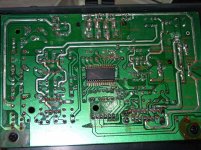
Then pins 4, 5, 11 and 12 gives me hum...a trebly one haha.
What gets me is how it responded to bending the board and now it doesn't (I could guess something broke completely but I can't find where, I tested! I will test more anyway) and how it went from a faint sound and distorted if I increased the bass (through the amplifier's tone control) and now it doesn't since I touched some TDA7303 pin (the chip below) (now I remember I did that, idiot me again), but as I said with the headphones it's working okay, and I guess is the same DPS for both outputs...!
And about the microcontroller. I say because on the one hand, when I'm testing sometimes it start working weirdly like swithcing too slow or too fast, and then there's this thing that when you plug the amp to grid it powers on, while mine get in stand by and you have to power it on with the power momentary action button in the front or the remote...But my brother told me it was always like that...And of course I have no idea how it works so for me, given my ignorance, is a possibility.
I'm thinking of tracing the circuit, at least for the part after the preamp because the problem have to be there, the part of the headphone amplifier is fine and the TDA7379 part have the problem.
But you tell me what to do next. I can take more pictures of even video if you need!
And 9 goes from 4.4 to 4.5 mV (I put the multimeter in "2000m" and gives me 004-005, and in "200m" 04.4-04.5) But depending where I touch the ground: if I touch it from the amplifier's power supply it gives me that reading, but if I use pin 8 it gives me 03.8mV, which of course makes sense since pin 8 is 0.07mV (?).
Just above is a 1000uF 25v electrolytic capacitor that is all stained, surely in perfect conditions like the rest, and a ceramic one (couldn't see the value). But I don't have a capacitor that value lying around right now. I have a 2200uF 35v but I don't think it will fit there and of course I
Then pins 4, 5, 11 and 12 gives me hum...a trebly one haha.!
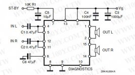
I assume the IC is using the following circuit taken from the datasheet. Pin 9 and 8 should be zero as they go to the grounds so i am very concerned if the PCB track to pin 9 is broken or not grounded. Pin 8 of the IC goes to the star ground, so that looks perfect. Pin 9 (signal ground) does not seem to connect to the ground, in your diagram it goes to the HP socket. I would closely trace pin 9 (the signal ground) and figure where it connects to the ground and by what means it connnects to the ground. One way would be to check with the power off, using your ohm meter the resistance from pins 8 and 9 to the ground. It should be 0.
If the 1000uf cap is brown colored, it could be not working which also could lead to instability and poor performance of the TDA7379 IC , you could try soldering your 2200uf cap in parallel to it if the previous tests dont show anything.
As a last resort, you could consider replacing the TDA7379.
Last edited:
I assume the IC is using the following circuit taken from the datasheet.
I think so. The only important difference I can see now is that 6 instead of 47uF is 10 uF, which is one I replaced. Then I can't confirm some of the other values.
I would closely trace pin 9 (the signal ground) and figure where it connects to the ground and by what means it connnects to the ground.
This is how, red traces are the jumpers:
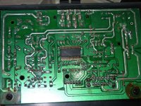
One way would be to check with the power off, using your ohm meter the resistance from pins 8 and 9 to the ground. It should be 0.
Pin 8 gives me between 0.2 and 0.3 Ohms
Pin 9 gives me 0.3 Ohms
From 8 to 9 also 0.3 Ohms
If the 1000uf cap is brown colored, it could be not working which also could lead to instability and poor performance of the TDA7379 IC , you could try soldering your 2200uf cap in parallel to it if the previous tests dont show anything.
Did it, no change. The only thing to notice is that at first I soldered badly and it detached while testing it and the lights in the front panel flickered and the faint sound from the speakers went away. Soldered correctly and all same as usual.
As a last resort, you could consider replacing the TDA7379.
Yeah, but I don't know if I'm brave enough to do it. I may end up destroying the PCB as I'm not very skilled desoldering and soldering. I already destroyed some other PCBs doing that, hehe (luckily weren't important). I may end up taking this thing to a technician...grrr!
I don't wan't to try to replace the front panel with the one from my amp or measure my amp values to compare, etc, because when dissasembly the unit you have to basically brake it, which of course I don't want to... If it wasn't for that I would have done it already...
Pin 8 gives me between 0.2 and 0.3 Ohms
Pin 9 gives me 0.3 Ohms
From 8 to 9 also 0.3 Ohms
I may end up taking this thing to a technician...grrr!
I /QUOTE]
Pins 8 and 9 are well grounded. I agree with you, i think you should take it to a technician who could easily figure out what is wrong with his equipment like scopes etc. We have done some initial test which show the PCB connections are good. It's a intermittent fault which is likely easily fixable so The safest thing is to take it to someone how has more advanced gear.
NOO! Guess what!?
I tried to connect the speaker I was using to test, to where it was (a small computer speaker amplifier) and it wasn't working!
It seems that time when I was testing and flexing the board making the sound come and go, the amp blow the speaker up and a resistor, the R137, look in the photo, one of the 2R2 SMD type ones in the top, the second one from left to right, is giving me 164.7 Ohms while the rest gives me 2.5 Ohms! So I was losing time (and your time) since more than a week ago!!!
I tested a good speaker (from my C200) straight to the TDA7379 and is working fine. I checked lanes and all fine. The only thing is that resistor. So when I connect the good speaker to the speaker terminal it doesn't work on only one side, it does in the other (left or right).
What I don't know is the function of those, could be the speaker terminal has some sort of protection?
Last edited:
I have some interesting readings with the "diode" function (or whatever is called) of the multimeter between the R136 to 139 resistors and the terminals, so there might be some protection inside (?). Let me find some more and I tell you what are those. I think a cable is also broken.
- Status
- This old topic is closed. If you want to reopen this topic, contact a moderator using the "Report Post" button.
- Home
- Amplifiers
- Chip Amps
- TDA7379 Based amplifier problem.