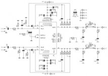
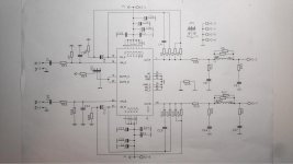
The schematic appears to follow the PCB and the values don't seem far away from the application notes. A few are different such as 22k instead of 20k for the Rf and Rf2.
Are you able to elaborate a little? What is badly wrong with the schema?
I have realised that the silk screen on the board is labelled 28v-GND-28v at the AC input - but the schematic shows the rectified voltage as being +/-28VDC
So using a modified version of Tom's calculator, as you both mentioned, a transformer of 22-0-22 250-300va will cover a 4 ohm load or 180-160va if restricted to 8 ohm loads (assuming Vcc=28, Cf=dB).
I'm guessing the output power from 16 ohms wouldn't be worth bothering with?
As far as I can see the schematic as given has nothing to do with a proper operation of an LM4780
Are you able to elaborate a little? What is badly wrong with the schema?
I have realised that the silk screen on the board is labelled 28v-GND-28v at the AC input - but the schematic shows the rectified voltage as being +/-28VDC
So using a modified version of Tom's calculator, as you both mentioned, a transformer of 22-0-22 250-300va will cover a 4 ohm load or 180-160va if restricted to 8 ohm loads (assuming Vcc=28, Cf=dB).
I'm guessing the output power from 16 ohms wouldn't be worth bothering with?
Thanks Mark. I've been staring at the schematic for ages trying to figure out how it works (it doesn't seem like it should) and that's because the schematic is a pretty bad inaccurate copy.
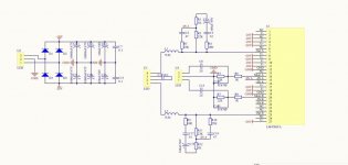
I managed to find the correct schematic on another thread from 5 years ago and it makes a whole lot more sense now.
Regarding the 10R resistors, I found the following quote that might be of interest:
I managed to find the correct schematic on another thread from 5 years ago and it makes a whole lot more sense now.
Regarding the 10R resistors, I found the following quote that might be of interest:
REACTIVE LOADING
It is hard for most power amplifiers to drive highly capacitive loads very effectively and normally results in
oscillations or ringing on the square wave response. If the output of the LM4780 is connected directly to a
capacitor with no series resistance, the square wave response will exhibit ringing if the capacitance is greater
than about 0.2μF. If highly capacitive loads are expected due to long speaker cables, a method commonly
employed to protect amplifiers from low impedances at high frequencies is to couple to the load through a 10Ω
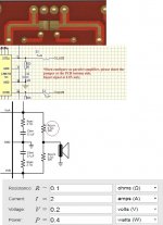
resistor in parallel with a 0.7μH inductor. The inductor-resistor combination as shown in the Figure 6 isolates the
feedback amplifier from the load by providing high output impedance at high frequencies thus allowing the 10Ω
resistor to decouple the capacitive load and reduce the Q of the series resonant circuit. The LR combination also
provides low output impedance at low frequencies thus shorting out the 10Ω resistor and allowing the amplifier to
drive the series RC load (large capacitive load due to long speaker cables) directly.
Attachments
R13 - 14 should be 2.7 ohms. And, if you use the stability parts in the feedback then Cc (220pF) is also missing.
Thanks for the pointers Mark.
I'm getting myself confused with the calculations:
If I were to make this board parallel (connect the jumper between 'R OUT' and 'L OUT') for LH channel and then do the same again for a RH channel, what would the effect be in terms of power supply requirement?
For instance if I have 22VAC/~30VDC supply for a 4 ohm load expecting to be 250-300VA, what would the VA requirement be if I join the outputs on the board and add another board?
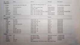
Does anyone have a BOM for the board from the first post ? I have 2 boards from audiomodule.eu ,but no values for elements.I was searching net but no luck for this bords.
Regards
zoky2
Sorry, I can't find any details of what's fitted to that particular board.
...If I were to make this board parallel (connect the jumper between 'R OUT' and 'L OUT')....
Don't do that without thinking!!!!
Say you have a 1% difference between amplifiers. At some moment, one is at 20V, the other at 20.2V. This is a 0.2V difference across the jumper. The amplifiers' output resistance may be less than 0.01 Ohms. Say the jumper is similar. 20V across the 8 Ohm load is 2.5 Amps to load, but 0.2V across 0.03 Ohms jumpering is 6.6 Amps of waste current and heat in the chip!
Thanks for the warning PRR.
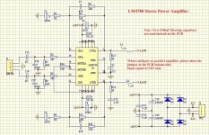
The schematic says to 'short out the jumper' and the PCB is designed with a shorting link..
But looking at the datasheet, it suggests 2x 0.1 ohm 3W resistors in series with the output in the centre.
I take it that this would work as it would reduce the 6.6A/1.3W to 2A 400mW?
edit: the audio sector boards appear to use 0.15R 3w power resistors (output).
Attachments
Last edited:
Hello everybody,
I just stumbled across this thread for the same reason as OP, as it turns out, audiomodule.eu is down and I never received the PCB schematic and BOM via email, but I did get them printed out with my purchase.
After a long search I managed to find them, hope this does the trick.
Best regards.
I just stumbled across this thread for the same reason as OP, as it turns out, audiomodule.eu is down and I never received the PCB schematic and BOM via email, but I did get them printed out with my purchase.
After a long search I managed to find them, hope this does the trick.
Best regards.
Attachments
Last edited:
- Status
- This old topic is closed. If you want to reopen this topic, contact a moderator using the "Report Post" button.
- Home
- Amplifiers
- Chip Amps
- Looking for the Circuit drawing of this LM4780 Board