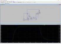
They will sit underneath a small side speaker with a Visaton B80 element. Powered by a small 36V SMPS. This is what I tried to do with this layout.
Using the LM3886 ground pin as a star ground for input, Ri, Ci, Rsn, Csn.
Using SMD components alowing me to put Rf1, Rf2 etc very close to the LM3886 pins.
Cs is a 220u low ESR with a 0.1u MLCC very close to the pins.
C and Ci are polyester caps.
The output cap will be mounted parallell to the board, not standing up to fit the case.
Comments? I can upload the KiCAD files in case anyone is interested.
Edit: The MMBT3904 had the wrong footprint. Will correct
Attachments
Last edited:
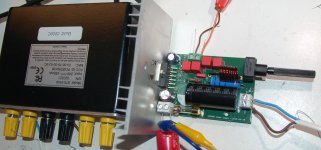
It is working?
Interesting. Have you built it? How does it sound?
Comments? I can upload the KiCAD files in case anyone is interested.
Interesting. Have you built it? How does it sound?
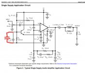
Hello, the circuitry around mute seems that it is not properly implemented (particularly I am talking about capacitor C11 position). Even in the datasheet it seems wrong. The best way to see this is if you have a look at internal schematic and symmetrical power supply schematic. The capacitor in that schematic is tied between GND and MUTE pin. They say that you need to draw equal to or more than 0.5mA to turn it on and on symmetrical power supply schematic the capacitor is there to slow down the slope of the current. On single supply schematic the capacitor does exactly the opposite.
In my opinion the capacitor should be tied between Q1 emiter and MUTE pin. In that case, you also must ensure that Q1 Vbe does not get reversed during shutdown because MUTE capacitor may dump the stored energy into this junction.
In my opinion the capacitor should be tied between Q1 emiter and MUTE pin. In that case, you also must ensure that Q1 Vbe does not get reversed during shutdown because MUTE capacitor may dump the stored energy into this junction.
Comments? I can upload the KiCAD files in case anyone is interested.
Arrgh KICAD !
Excellent for number of library components but full of bugs.
They even admit it on the website especially concerning latest versions.
They seem to let stuff out without properly debugging it.
What do you expect for free though ?
You pay your money and you take your choice.....
FWIW, KiCAD is absolutely worth the money
Worth the money? It's free, isn't it?
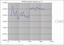
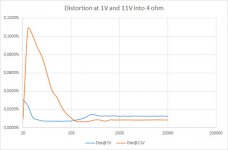
Now, for the interesting part and here is where I expect to be educational... I measured it with my old HP8903A that has a baseline distortion of about 0.005%
The amp was fed from a TTI power supply at 35V and loaded by a 4 ohm resistive load. At low levels the amp adds very little to the baseline, but at higher levels I see a sharp increase in distoriton at lower frequencies. Based on what I see on the monitor output of the 8903A it is basically 2f, modulated with something. Any ideas what might cause this? @tomchr perhaps?")
(oh yes, graphs are prettier in Office 2016 than in 2010)
The amp was fed from a TTI power supply at 35V and loaded by a 4 ohm resistive load. At low levels the amp adds very little to the baseline, but at higher levels I see a sharp increase in distoriton at lower frequencies. Based on what I see on the monitor output of the 8903A it is basically 2f, modulated with something. Any ideas what might cause this? @tomchr perhaps?
(oh yes, graphs are prettier in Office 2016 than in 2010)
Attachments
Last edited:
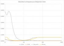
I did some comparions to a cheap PCB I bought on eBay for prototyping. Schematic is the same and components are almost identical apart from the eBay one having electrolytics for C and Ci. As expected does the eBay PCB have pretty horrid THD at low frequencies, but adding a 100u across Ca fixes that. It does have somewhat higher THD at high frequencies possibly because of the layout.
Attachments
It is the same either way. The circuit thumps even if Rm is not connected to ground and if the cap is connected to ground or Vcc/2. With a single supply, the output of the amp will jump to Vcc/2 when the amp is enabled and I will get a thump no matter what. In fact, I can make it happen with just a speaker and an electrolytic. Apply 18V (Vcc/2) and I have a thump.
Last edited:
You hear the thump because the circuit loads the output capacitor to 1/2 Vcc.
A single supply amplifier is a "virtual ground".
Make the output capasitor also a virtual ground an see if it helps. (i.e. 2 output capacitors, one to Vcc and one to ground, speaker - to the mid connection point.)
A single supply amplifier is a "virtual ground".
Make the output capasitor also a virtual ground an see if it helps. (i.e. 2 output capacitors, one to Vcc and one to ground, speaker - to the mid connection point.)
- Status
- This old topic is closed. If you want to reopen this topic, contact a moderator using the "Report Post" button.
- Home
- Amplifiers
- Chip Amps
- Yet another LM3886 Layout. Single-supply