 Title changed at OP's request.
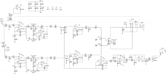
I am thinking of building the attached preamp to go with my Cordell Super Gainclone and would like to know if anyone can help with regards to the coupling cap values. They appear unnecessarily high and are currently 100uf and polarized.
From what I can find on the forum, it is better to use polyester or polypropylene caps. I have some 2.2uF and 4.7 uF polyester caps and wondering if I could use them instead.
Thanks for any help.
Attachments
Last edited by a moderator:
the 100uF coupling high value is intended to short the current noise of the opamp.
the noise is then determined by R7 and the series resistor in the input line,plus any high input impedance as source. that why you find the same value cap in series with R7.
the noise contribution is still minimal and you only find a minimal maybe measurable increase in the subLF region when the input coupling cap is reduced.
Thanks to all for the great input.
Shoker. That's easy enough to do!In most cases 4,7uf would be enough
FauxFrench. P3 is 10kIt depends on the value of the volume potentiometer P3-VOLA/VOLB.
basreflex. You think I should not replace the electrolytic caps then? The only reason I would even think of making a change to the design is because I thought that electrolytic caps were not good for audio coupling.the 100uF coupling high value is intended to short the current noise of the opamp.
the noise is then determined by R7 and the series resistor in the input line,plus any high input impedance as source. that why you find the same value cap in series with R7.
the noise contribution is still minimal and you only find a minimal maybe measurable increase in the subLF region when the input coupling cap is reduced.
Electrolytics are fine for audio coupling, provided that the right value is used. Note that not all the electrolytics in that circuit are coupling caps; some are part of the feedback arrangements and if you put a lower value here you may get an LF boost.
It is normal for electrolytic coupling caps to have higher values than would be needed for film coupling caps.
It is normal for electrolytic coupling caps to have higher values than would be needed for film coupling caps.
Electrolytics are fine for audio coupling, provided that the right value is used. Note that not all the electrolytics in that circuit are coupling caps; some are part of the feedback arrangements and if you put a lower value here you may get an LF boost.
It is normal for electrolytic coupling caps to have higher values than would be needed for film coupling caps.
Thanks for that DF96! I may have phrased my original question incorrectly. Perhaps it should have read "Should I Use Smaller Value Polyester?" as I don't want to mess up what might be a perfectly good design.
I disagree. Electrolytics used as coupling caps have WAY more distortion than film caps.Electrolytics are fine for audio coupling, provided that the right value is used.
FauxFrench. P3 is 10k
Thanks for the information.
The potentiometer is 10K. The output of the potentiometer goes to two (each channel) non-inverting inputs without further loading and to a single inverting amplifier stage for the Sub-woofer. That inverting amplifier stage loads the output of each potentiometer with another 10K. At full volume, the 10K from the potentiometer is in parallel with the 10K from the inverting amplifier stage - thus, with 5K as the result.
100uF and 5K leaves a cut-off frequency of 0.32Hz. Ample margins.
With a change to 4.7uF, the 5K impedance leaves a cut-off frequency of 6.8Hz. A lower cut-off frequency of 6.8 Hz is reasonable. At least your speakers can't do better.
Yep, you can use 4.7uF foil.
NB: That is for C17 and C18. For C28 and C29 (balance) it depends on the input impedance of your power amplifier. Below 5K you need more than 4.7uF
Last edited:
Thanks for the information.
The potentiometer is 10K. The output of the potentiometer goes to two (each channel) non-inverting inputs without further loading and to a single inverting amplifier stage for the Sub-woofer. That inverting amplifier stage loads the output of each potentiometer with another 10K. At full volume, the 10K from the potentiometer is in parallel with the 10K from the inverting amplifier stage - thus, with 5K as the result.
100uF and 5K leaves a cut-off frequency of 0.32Hz. Ample margins.
With a change to 4.7uF, the 5K impedance leaves a cut-off frequency of 6.8Hz. A lower cut-off frequency of 6.8 Hz is reasonable. At least your speakers can't do better.
Yep, you can use 4.7uF foil.
NB: That is for C17 and C18. For C28 and C29 (balance) it depends on the input impedance of your power amplifier. Below 5K you need more than 4.7uF
Nice. I am definitely going to have to do some more studying
 until I can work this problem as you have. Thanks very much.
Thanks for the information.
The potentiometer is 10K. The output of the potentiometer goes to two (each channel) non-inverting inputs without further loading and to a single inverting amplifier stage for the Sub-woofer. That inverting amplifier stage loads the output of each potentiometer with another 10K. At full volume, the 10K from the potentiometer is in parallel with the 10K from the inverting amplifier stage - thus, with 5K as the result.
100uF and 5K leaves a cut-off frequency of 0.32Hz. Ample margins.
With a change to 4.7uF, the 5K impedance leaves a cut-off frequency of 6.8Hz. A lower cut-off frequency of 6.8 Hz is reasonable. At least your speakers can't do better.
Yep, you can use 4.7uF foil.
NB: That is for C17 and C18. For C28 and C29 (balance) it depends on the input impedance of your power amplifier. Below 5K you need more than 4.7uF
Nice. I am definitely going to have to do some more studying. High Pass filter?
until I can work this problem as you have. Thanks very much.
Last edited:
Thanks for the information.
The potentiometer is 10K. The output of the potentiometer goes to two (each channel) non-inverting inputs without further loading and to a single inverting amplifier stage for the Sub-woofer. That inverting amplifier stage loads the output of each potentiometer with another 10K. At full volume, the 10K from the potentiometer is in parallel with the 10K from the inverting amplifier stage - thus, with 5K as the result.
100uF and 5K leaves a cut-off frequency of 0.32Hz. Ample margins.
With a change to 4.7uF, the 5K impedance leaves a cut-off frequency of 6.8Hz. A lower cut-off frequency of 6.8 Hz is reasonable. At least your speakers can't do better.
Yep, you can use 4.7uF foil.
NB: That is for C17 and C18. For C28 and C29 (balance) it depends on the input impedance of your power amplifier. Below 5K you need more than 4.7uF
These will be the amps that receive the input. My Cordell Super Gainclone and my SC200
Attachments
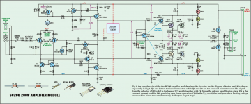
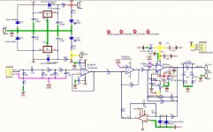
These will be the amps that receive the input. My Cordell Super Gainclone and my SC200
The SC200 should have an input impedance near 12K, the Cordell >100K. So, use some more of your 4.7uF. For the Cordell even 2.2uF.
The SC200 should have an input impedance near 12K, the Cordell >100K. So, use some more of your 4.7uF. For the Cordell even 2.2uF.
That's great!
I will be switching the input from one amp to the other, so I'd be better to use 4.7uF all round then; assuming of course that they will be an improvement on the 100uF electrolytics!
For what it's worth, Nelson Pass uses electrolytics on both the inputs and the outputs of the Amp Camp Amp, so I assume there's nothing wrong with them, as long as the capacitance is high.
Consider this. Given a 100uf cap in series with a 5k load, a 20 hz 2 volt input signal will result in a .032 volt drop across the cap. It's contribution is negligible.
Consider this. Given a 100uf cap in series with a 5k load, a 20 hz 2 volt input signal will result in a .032 volt drop across the cap. It's contribution is negligible.
That's great!
I will be switching the input from one amp to the other, so I'd be better to use 4.7uF all round then; assuming of course that they will be an improvement on the 100uF electrolytics!
On the improvement it is very difficult to say. Foil capacitors are no doubt more linear than el.caps and have less leakage current. But, there are many designs, known to be very good, that use el.caps in the signal path. Further, special audio grade el.caps are made and sold at high prices by well reputed manufacturers.
Worth the money and necessary? If I can I use foil capacitors to be on the safe side.
For the low level coupling, the metalized polypropylene caps work fine, and plenty to choose from, lots of discussions on the web as to how they tend to sound, etc.
Polyester will be better than the electrolytic types.
A smaller sized part that I like is the Wima MKP10, 4.7uf 100v.
Polyester will be better than the electrolytic types.
A smaller sized part that I like is the Wima MKP10, 4.7uf 100v.
On the improvement it is very difficult to say. Foil capacitors are no doubt more linear than el.caps and have less leakage current. But, there are many designs, known to be very good, that use el.caps in the signal path. Further, special audio grade el.caps are made and sold at high prices by well reputed manufacturers.
Worth the money and necessary? If I can I use foil capacitors to be on the safe side.
For the low level coupling, the metalized polypropylene caps work fine, and plenty to choose from, lots of discussions on the web as to how they tend to sound, etc.
Polyester will be better than the electrolytic types.
A smaller sized part that I like is the Wima MKP10, 4.7uf 100v.
I'm hoping that Cbb22 Metallized Polypropylene film caps will be ok (better than electrolytic,) as they are cheap enough to get!
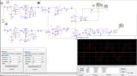
I've simulated the circuit at a rather low frequency of 16Hz (lower than subwoofer range?) using 4.7uF for C1, C17, C22, C29 on the top half of the circuit and left the bottom at 100uF. There's not much difference in the output, just slightly lower. At more reasonable frequencies, there appears to be no difference. The output from the subwoofer (not shown) looks identical.
Attachments
I disagree. Electrolytics used as coupling caps have WAY more distortion than film caps.
Not if they are used correctly. There are MANY well built and very good sounding audio devices that use electrolytics for coupling applications. For filter circuits not so much. Keep Fc of the circuit really low, less than 1 Hz for example, and they won't have any audible impact at all.
Mike
True, but deeply deeply misleading. Yes, electrolytics have way more distortion - but distortion will be so low that you won't notice it. Let us use numbers:dotneck335 said:I disagree. Electrolytics used as coupling caps have WAY more distortion than film caps.
100uF feeding a 10k load will have an LF rolloff at 0.16Hz. A 20Hz signal will develop 0.8% of its magnitude across the cap. Assume the cap is really bad and generates 1% distortion. The distortion seen by the amp will then be 0.008%. A film cap might have distortion 100-10000 times lower. So yes, 0.008% is way bigger than 0.0000008%.
Compare this with speakers having 10% distortion (similar for a SET amp) and perhaps 1-2% added by an FX box in the studio to add 'warmth'.
- Status
- This old topic is closed. If you want to reopen this topic, contact a moderator using the "Report Post" button.
- Home
- Amplifiers
- Chip Amps
- Preamplifier For Cordell Super Gainclone and SC200