I did the math like this:
1. The 3886 is configured with a gain of 12 and can reach (Vsupply - 3V) on each rail before clipping. For +/- 28v supply, this means I want to drive it to max +/- 25V. Say 24V to make it round. So a gain of +/- 2V and a gain of 12x will result in +/- 24V swing.
2. The 49710 can swing +/-14V before clipping so to get the +/-2V for the 3886, I have to divide it by 7.
If you want to you can get closer to the rails, also you could use +-17V supplies for the 49710.
As for the GM/PM discussion, I guess my lack of knowledge/terminology shows - you need to break the loop (as you have done) to see the feedback as it will be presented to the inverting input otherwise you're just looking at a virtual ground... hopefully someone else can advise whether your simulation is accurate in that respect.
Here's the schematic in TINA-TI if anyone is interested in playing with it.
There are both parts - the inverting and non-inverting, some speaker simulation and a small input filter.
View attachment 738242
Enjoy
There are both parts - the inverting and non-inverting, some speaker simulation and a small input filter.
View attachment 738242
Enjoy
Here's the schematic in TINA-TI if anyone is interested in playing with it.
There are both parts - the inverting and non-inverting, some speaker simulation and a small input filter.
View attachment 738242
Enjoy
For anyone downloading this, note that the SPK+ terminal is connected to ground by mistake due to some tests that I was doing.
If you want to you can get closer to the rails, also you could use +-17V supplies for the 49710.
As for the GM/PM discussion, I guess my lack of knowledge/terminology shows - you need to break the loop (as you have done) to see the feedback as it will be presented to the inverting input otherwise you're just looking at a virtual ground... hopefully someone else can advise whether your simulation is accurate in that respect.
I just did some clipping tests and it's looking promising.
Here is the LM3886 clipping:
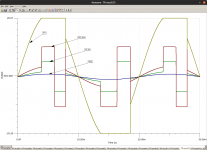
It's obvious that the 49710 is trying to correct the clipping and goes into saturation.
There are some really bad spikes as well in there:
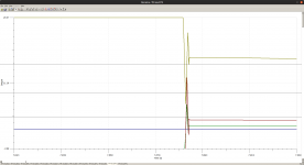
And here is the 49710 clipping:
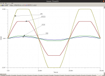
Much nicer. I had to change the 7:1 divider for a 6:1 divider as my math was off.
Now the voltage swing is around +/- 23V out of a 28V supply for the LM3886 so there's enough margin for it before it clips.
Thanks for the idea simonra!
PM, GM are simulated open loop.
I don't show any simulations of a composite amp on my website. I show loop simulations of the LM3886.
I meant to say the that I opened the loop like you do for the LM3886.
I later found this https://training.ti.com/ti-precision-labs-op-amps-stability-3 and tried it as well. The results are in post 18
No. The PM/GM (which are loop parameters, hence simulated open loop) are just one piece of the puzzle.
I start with the loop analysis, because if the loop isn't stable there's no point in simulating anything else. I then simulate the closed loop response to make sure I don't have excessive peaking and to pick out potential issues that I may have missed. I simulate the transient response to see how the amp behaves when slewing, when it reaches clipping, and on hard clipping. I look at the DC operating point to see the DC offset. I look at the noise performance. And take a quick glance at the THD to see if anything is fundamentally broken.
I simulated the closed loop peaking and transient response as done here: TI Precision Labs - Op Amps: Stability 4 | TI.com Video
They seem ok as far as I can tell (results in post 18)
This is the part I'm most afraid of - testing it out. I have an oscilloscope (a DS1054) and a signal gen but not a spectrum analyzer nor a lot of spare time. Simulations are easy to run and tweak - type a value there, add a wire there etc - but real bench testing requires a lot of time.In a production environment I sweep these parameters across supply voltage and temperature as many of these characteristics vary across temperature. I don't recall if the LM3886 macro model takes temperature into account. It might. I know it laughs at the power supply voltage. Nothing power supply related is simulated with the LM3886 macro model.
Once I have a circuit that I feel reasonably confident in, I'll build it. I then correlate reality with simulation. Over time, I've developed a sense of the strengths and weaknesses of the LM3886 model, which allows me to shorten the development time. Basically, I know how far off target to aim in order to hit the target in reality.
As I said in the first post - even if it works, I really want to know that it works for the right reasons, so I will do bench testing even if it sounds ok.
Based on your questions so far, I recommend taking half a step back and brushing up on some stability theory. Chapter 8 in Franco is a good place to start. I'm sure there's a corresponding chapter in Yung. You can find the full references here: References.
In general, I highly recommend Franco for anyone interested in working with opamps and amplifiers in general. The latest edition (3rd) is absurdly expensive, in particular since it hasn't changed in 15+ years, but the 2nd edition is every bit as good (there were very few changes between editions) and can be found on the used market for less.
Tom
I definitely need to get up to speed with this topic indeed. Fortunately it's very interesting as well so makes for some nice reading.
Thanks a lot for the references. I cannot believe how much info you can find today just by asking in the right places.
This is the part I'm most afraid of - testing it out. I have an oscilloscope (a DS1054) and a signal gen but not a spectrum analyzer nor a lot of spare time. Simulations are easy to run and tweak - type a value there, add a wire there etc - but real bench testing requires a lot of time.
As I said in the first post - even if it works, I really want to know that it works for the right reasons, so I will do bench testing even if it sounds ok.
The problem with a design like this is if you get it right the noise and distortion should be so low they're difficult to measure. I think you can get a long way with a decent sound card, there's lots of information here on how to do that. A cheap analogue scope is pretty useful too.
I definitely need to get up to speed with this topic indeed. Fortunately it's very interesting as well so makes for some nice reading.
Thanks a lot for the references. I cannot believe how much info you can find today just by asking in the right places.
My learning process goes:
read -> think I understand something -> build something -> realise I didn't understand properly -> read some more etc.
I think you have to factor in failures... I've got a drawer full of PCBs that didn't work properly (or at all) but I learned a lot more from those than the designs that worked first time.
[...] nor a lot of spare time. Simulations are easy to run and tweak - type a value there, add a wire there etc - but real bench testing requires a lot of time.
Simulations are certainly the fastest and cheapest way to "build" a circuit. Do expect to spend significant time in the lab with a composite amp, though. They do have a nasty way of pushing the parts into operating corners not characterized well by the simulation models. It's more fun to have your amp generate lots of heat in a load resistor than to have it fry your speakers, so take your time there. It's not like you have to meet a set production schedule.
For a more turnkey solution, the basic LM3886 is pretty tough to beat. All the information you need is in the data sheet (and on my website).
Tom
Schematic, PCB
I started working on the schematic & PCB on EasyEDA.
Here's the link:
amp-LM3886-composite - EasyEDA
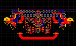
To keep traces short in the feedback loops the PCB gets very interesting, especially due to the paralleled LM3886. I had to flip the second one in each parallel group, so one LM3886 goes on the top layer and the second one on the bottom layer so they will alternate on the PCB.
The PCB is work in progress - I only have the non-inverting part partially done: the 3886's, the 40720 and the 2277 servos. Due to the flipping of the second 3886 the layout got pretty symmetrical which should help to keep the 2 paralleled branches working similarly (I hope).
Still working on routing the power and quiet grounds.
I had to populate both layers (top for signal components and bottom for decoupling mostly).
Also, the components are SMD as I really like to do SMD and they are a bit crammed together.
Most of the parts are from LCSC as they tend to be 2-5x cheaper for passives (metal film for resistors) and ~2x cheaper for chips.
A few resistors are still from Digikey as I couldn't find them on LCSC.
I started working on the schematic & PCB on EasyEDA.
Here's the link:
amp-LM3886-composite - EasyEDA

To keep traces short in the feedback loops the PCB gets very interesting, especially due to the paralleled LM3886. I had to flip the second one in each parallel group, so one LM3886 goes on the top layer and the second one on the bottom layer so they will alternate on the PCB.
The PCB is work in progress - I only have the non-inverting part partially done: the 3886's, the 40720 and the 2277 servos. Due to the flipping of the second 3886 the layout got pretty symmetrical which should help to keep the 2 paralleled branches working similarly (I hope).
Still working on routing the power and quiet grounds.
I had to populate both layers (top for signal components and bottom for decoupling mostly).
Also, the components are SMD as I really like to do SMD and they are a bit crammed together.
Most of the parts are from LCSC as they tend to be 2-5x cheaper for passives (metal film for resistors) and ~2x cheaper for chips.
A few resistors are still from Digikey as I couldn't find them on LCSC.
Do you need servo for each LM3886 or one should be enough for each pair ?
Tom used in his parallel86(lm4780) one servo for both halves of the chipamp.
I think that's because the 2 halves of the lm4780 are very similar and will have a near identical offset.
I believe Tom managed the DC offset within the feedback loop of his mod686 amp negating the need of a separate servo. The TI application note for the BPA200 amp using 3 paralleled LM3886's has a servo for each chip. This is more complicated but probably a better way to go because you are controlling each chips output offset individually.
simulation files link
Jeanlemotan: this link does not seem to work for me.
Walt
Here's the schematic in TINA-TI if anyone is interested in playing with it.
There are both parts - the inverting and non-inverting, some speaker simulation and a small input filter.
View attachment 738242
Enjoy
Jeanlemotan: this link does not seem to work for me.
Walt
Jeanlemotan: this link does not seem to work for me.
Walt
Not sure why it didn't get attached properly. Here's a link from my google drive:
lm3886.zip - Google Drive
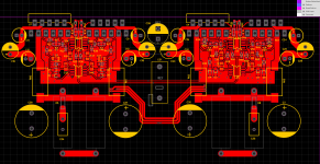
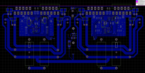
PCB is almost done. I'm missing the power and speaker blade connectors and do double and triple check all the component footprints and connections.
Here's the top layer:
Bottom layer:
Both:
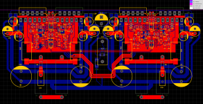
The thing I'm not sure about are the ground & power connections.
There are 3 grounds: high-power-ground (for the LM3886), low-power-ground (for the other opamps) and signal ground.
Since it's a bridged amp, the only use of the power ground is as a return for decoupling caps.
I have both power grounds connecting at the bottom-center of the board.
The signal ground is also starting there (bottom-center of the board) and goes through a 4R7 resistor. I use ground top and bottom planes for the signal ground only.
In an effort to keep things symmetrical and the length of power traces similar between both halves, the power traces don't connect on the board and will be fed through blade connectors in the center of each half right between the output resistor and inductor (so between R7 & L1 and R10 & L2).
Another thing I'm worried about is the fact that some power caps and the mute cap are very close to the heat sink. I chose 105 degree caps but I'm not sure what will happen long term.
Does this make any sense?
Here's the top layer:

Bottom layer:

Both:

The thing I'm not sure about are the ground & power connections.
There are 3 grounds: high-power-ground (for the LM3886), low-power-ground (for the other opamps) and signal ground.
Since it's a bridged amp, the only use of the power ground is as a return for decoupling caps.
I have both power grounds connecting at the bottom-center of the board.
The signal ground is also starting there (bottom-center of the board) and goes through a 4R7 resistor. I use ground top and bottom planes for the signal ground only.
In an effort to keep things symmetrical and the length of power traces similar between both halves, the power traces don't connect on the board and will be fed through blade connectors in the center of each half right between the output resistor and inductor (so between R7 & L1 and R10 & L2).
Another thing I'm worried about is the fact that some power caps and the mute cap are very close to the heat sink. I chose 105 degree caps but I'm not sure what will happen long term.
Does this make any sense?
PCB done
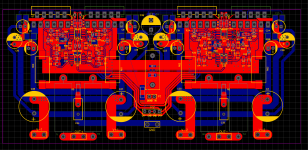
I routed the power, output and signal connectors and made the signal ground plane a bit bigger.
Since vias are almost free, I added a few in the power traces to get lower resistance between top and bottom layers near filter caps.
Not sure if there's anything else I'm missing in the schematic so this looks like it's ready for production.
Here is the BOM:
ID Name Designator Footprint Quantity Manufacturer Part Manufacturer Supplier Supplier Part
1 47u C11,C12,C9,C10,C19,C20,C24,C25 CP_6.3X11MM 8 ? LCSC C338236
2 33u C15,C18,C23,C28 CAP-8*11.5 4 ? LCSC C88840
3 1000u C37,C38,C3,C30 CAP-D16.0XF7.5 4 ? LCSC C131641
4 4.7u C4,C5,C13,C14,C16,C17,C21,C22,C26,C27,C52,C53 1210 12 ? LCSC C338107
5 0.1u C29,C7,C8,C54,C55,C56,C57,C58,C59,C60,C61,C62 C_0805 12 ? LCSC C116837
6 Low-Power P2 HDR-4X1/2.54 1 Header-Female-2.54_1x4 ReliaPro LCSC C124413
7 Pcb Spade V+1,GND,V-1,V+2,V-2,OUT+,OUT- 1287-ST_BLADE_CONNECTOR 7 ?
8 LM3886T U7,U4,U5,U11 TO220-11 4 ? LCSC C81907
9 1k R20,R22,R24,R25,R19,R26,R27,R28,R36,R38,R39,R40,R48,R50,R51,R52,R64,R65,R4 R_0603_HANDSOLDERING 19 ERA-6AEB102V PANASONIC LCSC C328638
10 22k R21,R23,R37,R49,R3 MINI_MELF-0204W 5 Digi-Key A127081CT-ND
11 1M R1,R2,R30,R41,R42,R53 R_0805_HANDSOLDERING 6 LCSC C332229
12 10k R17,R34,R29,R46,R57,R59 R_0805_HANDSOLDERING 6 LCSC C328719
13 220k R18,R35,R47,R58 R_1206 4 LCSC C340557
14 33 C1,C42,C44,C49 C_0603 4 ? LCSC C126560
15 3.3 C2,C43,C46,C50 C_0402 4 ? LCSC C88892
16 470n C6,C32,C45,C47,C48,C51 C_1206 6 ? LCSC C338107
17 BAS45AL D1,D2,D3,D4,D5,D6,D7,D9 MINI-MELF 8 ? Digi-Key 1727-4808-1-ND
18 0.1 R60,R61,R62,R63 5329 4 LCSC C252911
19 5.6k R6,R9,R16,R31 MINI_MELF-0204W 4 Digi-Key A127074CT-ND
20 4.7u C31 CAP 15MM 1 ? LCSC C280290
21 560p C33 C_0603 1 ? LCSC C178421
22 100n C34,C35 CAP-5.0-11*4.5 2 ? LCSC C314419
23 2.7 R5,R8 MINI_MELF-0207W 2 Digi-Key 749-1153-1-ND
24 10 R7,R10 R_AXIAL_POWER_L25.0MM_W9.0MM_P30.48MM 2 LCSC C62526
25 700n L1,L2 R_AXIAL_POWER_L25.0MM_W9.0MM_P30.48MM 2 ?
26 4.7 R11 MINI_MELF-0207W 1 LCSC C265621
27 4.7k R12 R_0805_HANDSOLDERING 1 LCSC C60816
28 1000u C39 CP_RADIAL_D10.0MM_P5.00MM 1 ? LCSC C238336
29 Input P1 HDR-1X2/2.54 1 2.54-1*2PFemale BOOMELE LCSC C49661
30 LME49720MA U1,U3 SOIC-8_150MIL 2 ? LCSC C84465
31 OPA2277UA U6,U8 SOIC-8_150MIL 2 OPA2277UA TI LCSC C24460
looks like it's ready for production.
Nah... Ready for prototyping maybe.
Best of luck on the meeting with reality. I hope it goes well.
Tom
board layout
Wow, that's a tight layout. Trying to look at that in any detail is giving me a headache
-this is likely a first pass, so you might want to separate the grounds and jumper them with wires in various ways during test to get the best result.
- I would suggest keeping the ground layer somewhat clear of the inverting and non-inverting inputs to avoid any parasitic capacitance to ground that may affect stability
- not sure about the 1000uf cap in the mute circuit, seems large. But that can be played with during test also.
you seem to be on the right track. I find that the prototype testing is more fun than the simulation part, hope you enjoy it also.
What are you planning to use as a dummy load?
Walt
The thing I'm not sure about are the ground & power connections.
There are 3 grounds: high-power-ground (for the LM3886), low-power-ground (for the other opamps) and signal ground.
Since it's a bridged amp, the only use of the power ground is as a return for decoupling caps.
I have both power grounds connecting at the bottom-center of the board.
The signal ground is also starting there (bottom-center of the board) and goes through a 4R7 resistor. I use ground top and bottom planes for the signal ground only.
In an effort to keep things symmetrical and the length of power traces similar between both halves, the power traces don't connect on the board and will be fed through blade connectors in the center of each half right between the output resistor and inductor (so between R7 & L1 and R10 & L2).
Another thing I'm worried about is the fact that some power caps and the mute cap are very close to the heat sink. I chose 105 degree caps but I'm not sure what will happen long term.
Does this make any sense?
Wow, that's a tight layout. Trying to look at that in any detail is giving me a headache
-this is likely a first pass, so you might want to separate the grounds and jumper them with wires in various ways during test to get the best result.
- I would suggest keeping the ground layer somewhat clear of the inverting and non-inverting inputs to avoid any parasitic capacitance to ground that may affect stability
- not sure about the 1000uf cap in the mute circuit, seems large. But that can be played with during test also.
you seem to be on the right track. I find that the prototype testing is more fun than the simulation part, hope you enjoy it also.
What are you planning to use as a dummy load?
Walt
You really have to use easyeda as a viewer and hide some layers, otherwise it's impossible. The photo is unreadable due to the ground planes.Wow, that's a tight layout. Trying to look at that in any detail is giving me a headache
That's an interesting idea, I'll think how I can do this.-this is likely a first pass, so you might want to separate the grounds and jumper them with wires in various ways during test to get the best result.
I removed the ground planes for now and connected the signal ground directly. It makes the PCB way easier to work with.- I would suggest keeping the ground layer somewhat clear of the inverting and non-inverting inputs to avoid any parasitic capacitance to ground that may affect stability
I went with a bigger value to get a big footprint. My mute resistor has to be sized for 4 LM3886, so ~2mA. I made it 4.7K just to be sure (so ~6mA at 28V), but that also forces me to increase the cap to keep the time constant. I also want to have a long(er) turn on time to allow the servos to do their magic. The footprint should allow me to play around with values.- not sure about the 1000uf cap in the mute circuit, seems large. But that can be played with during test also.
Now that I think about it I could just go for 10K and half the cap value and be done with it.
you seem to be on the right track. I find that the prototype testing is more fun than the simulation part, hope you enjoy it also.
What are you planning to use as a dummy load?
Walt
I'm not sure. Sometimes it can be frustrating as you cannot simply 'undo' things and any big mistake results in another PCB and 1 week of waiting and desoldering everything, then resoldering everything... This is why I got into software many years ago; Ctrl+Z is magic
For the dummy load I plan 4 resistors of 4ohm and 50W that I can combine to get various output resistances. I plan to bolt them to a heatsink and submerge them in water if they get hot, or just use a CPU heatsink + fan that I have laying around.
Last edited:
Don't forget to order some caps to put in parallel with the resistive load to form a reactive load. I generally test with 8 Ω || 1 nF, 2.2 nF, 4.7 nF, .... 4.7 uF. Run a square wave at various amplitudes into the amp and measure ringing and see how much capacitance you can drive before the amp becomes unstable.
Tom
Tom
I first built that circuit 25 years ago, but not with the LME49710. I used a gain of 5 for the 3886 with no problems. Shipped hundreds in subwoofers and never had a failure. I still use one as a bench amp. My instinct is that the tools allow for over-analysis. Building it you will learn what you need pretty quick. I have had no issues with offset or stability with no extraordinary efforts. The spice tools were primitive then so it was a build and see following the Pease model. Fortunately the LM3886 is pretty sturdy.
I'm about to do something similar with an APEX PA85 https://www.apexanalog.com/resources/products/pa85u.pdf and that I will be careful with, doing what simulations I can. Those are very expensive amp modules.
I'm about to do something similar with an APEX PA85 https://www.apexanalog.com/resources/products/pa85u.pdf and that I will be careful with, doing what simulations I can. Those are very expensive amp modules.
- Status
- This old topic is closed. If you want to reopen this topic, contact a moderator using the "Report Post" button.
- Home
- Amplifiers
- Chip Amps
- Composite amplifier: LM3886 + LME49710