It was working and apparently something came loose when I moved it from the bench to the audio room.
This is the right channel and the left channel works.
I dont know where to take voltage readings or to see what the signal looks like with a scope.
I put a 1khz signal in and tried to trace it through to the output and I got lost. Ditto reading voltages.
I tried comparing the voltages and waveform to the left channel but I dont know what to look for. For example, what the waveform should look like and where to look for it,
Attachments
If you move the amp from one site to another, first check cables, connectors, etc. Second, check power supplies (Irrelevant if both amps have one of them in common).
Third, simply, connect al speaker and touch the input connector, the speaker must hum. No instruments are needed in this case.
Third, simply, connect al speaker and touch the input connector, the speaker must hum. No instruments are needed in this case.
You write: "I dont know where to take voltage readings or to see what the signal looks like with a scope". I get the impression you have access to an oscilloscope and know a little about using it. Further, you mention you have a 1KHz signal source. I also assume you have a multi-meter (voltmeter/Ohm-meter).
Comparing the values between the channel that works and the channel that has become silent is intelligent.
You can then write to us what you measure.
If you for a start turn the amplifier ON, without a signal at the input, without speakers connected at the output and use your voltmeter in DC measurement position.
Keep the black measuring probe connected to PWR_GND and move the red measuring probe around to the different measuring points.
1) Measure the voltage on pins 1 and 5 on both ICs (channels). They should be the same value. What value(s) did you measure?
2) Measure the voltage on pins 4 and 7 on both ICs (channels). They should be the same value. What value(s) did you measure?
3) Measure the voltage on pin 3 on both ICs (channels). They should be close to the same value. What value(s) did you measure?
4) Measure the voltage on pin 9 on both ICs (channels). They should be close to the same value. What value(s) did you measure?
5) Measure the voltage on pin 10 on both ICs (channels). They should be close to the same value. What value(s) did you measure?
Last edited:
Thanks a lot for the systematic work. The first and last columns are particularly interesting.
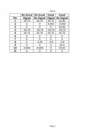
First column "NO GOOD / SIGNAL" (What does that actually mean? The channel that does not work but with signal at the input?), for that operating state the chip is muted (pin 8) and evidently there is no reaction at the output.
Last column "GOOD / NO SIGNAL" (What does that actually mean? The channel that works but without input signal?), here pins 1 and 5 are not connected as they should according to the schematics (they have a different voltage). Both output (pin 3) and inputs (pins 9 and 10) are pulled to the positive supply rail which is wrong.
Is it an amplifier you have build yourself on a board you made yourself?
Please clarify the the meaning of the two first lines NO GOOD/GOOD and SIGNAL/NO SIGNAL before I try to analyze the results in details and draw wrong conclusions.
Last edited:
This is how i did it.
Good = the amp that works
No Good = the amp that does not work
No Signal = no input signal
Signal = A 1 khz audio signal is connected.
I can tell that the amp is working correctly by the sound
coming from a speaker and by the amplified 1khz signal
as displayed by my scope. The good amp shows a highly
amplified 1khz signal on the scope whereas the no good
amp shows a flat line.
The 2 amplifiers i have built myself and the design belongs
to someone else based upon a LM3886.
The boards i bought from the same gentlenan who designed
the amp.
This is how i did it.
Good = the amp that works
No Good = the amp that does not work
No Signal = no input signal
Signal = A 1 khz audio signal is connected.
I can tell that the amp is working correctly by the sound
coming from a speaker and by the amplified 1khz signal
as displayed by my scope. The good amp shows a highly
amplified 1khz signal on the scope whereas the no good
amp shows a flat line.
The 2 amplifiers i have built myself and the design belongs
to someone else based upon a LM3886.
The boards i bought from the same gentlenan who designed
the amp.
Thanks for the precise reply,
Actually, the values of the "NO GOOD" amplifier look more correct than the values of the GOOD amplifier.
For the "NO GOOD" amplifier, the problem seems to be the MUTE input as pointed to by Tom. The MUTE input is supposed to be permanently tied towards the negative rail but for some reason it changes between -2.25V (probably un-muted) when you have no input signal and 0V (muted) when you have an input signal. This explains why you have no output from this amplifier when you have an input signal.
It may be due to a bad soldering though it should then be constant disregarding if there is an input signal or not.
R5 (10K) of the "NO GOOD" amplifier is the resistor that pulls the MUTE-pin toward the negative rail. Will you please measure the voltage (from PWR_GND) on both sides of that resistor R5 with signal and without signal?
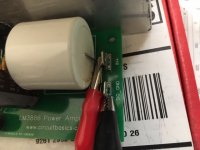
Is it possible that you post two photos of the board, one from the component side and one from the soldering side?
For the "GOOD" amplifier there is something weird as well. For a start, pins 1 and 5 are not connected as they should be according to the schematic. I draw this conclusion from the fact that you have different voltages on the two pins without signal. This is likely to be a bad soldering of either pin 1 or pin 5. Please check the solderings.
Last edited:
Thank you Tom, but why would I investigate this since the amp seems to be working ?Pin 8 is MUTE. Looks like the "no good" amp is muted when signal is applied. I'd try to figure out why.
I'd also investigate why you have DC on the output (Pin 3) of the "good" amp.
Tom
Resolder everything connected with pin 8. Your amp is likely in mute.
Thank you John, I will do that.
Thank you Tom, but why would I investigate this since the amp seems to be working ?
Tom is right. You may have an output signal from an amplifier that is wrongly connected. Such may mean you have a less good performance or even that the wrong connection may leave the amplifier to break down after short time of operation.
A bit like if the motor in your car turns but only with a thick smoke from the exhaust pipe. It is likely not to last for long.
The rest position at the positive voltage rail is a serious flaw and the missing connection between pins 1 and 5 perhaps (a part of) the reason.
Re pin 8, this is what the data sheet says.
Pin8 Openorat0V,Mute:OnCurrentoutofPin8 > 0.5mA,11580dB(min)Mute:Off
I am trying to make sense of that and this is how I interpret it so please correct my interpretation.
1) If the pin is open or at 0V, it means mute, ie the chip turns off.
I dont know what open means. Can the chip tell if there is no signal vs 0V ?
2) If the current out is greater than 0.5ma, then the chip is switched on, if something is greater than 11580dB (Huh ?).
I am measuring voltages not current nor the mysterious dB. I had thought dB had to do with audio listening levels. IE, 90dB is front row orchestra,
Total confusion. Help !
MUTE pin 8 is un-muted (chip active) if more than 0.5mA leaves from the pin. In such case, you have typically 115dB damping and at least 80dB. The datasheet page 7 shows what is inside the chip for pin 8. One basis-emitter drop, a 1K resistor and two series-coupled diodes. When a minimum of 0.5mA runs through that you have a voltage drop of more than two volts. This you see for the "GOOD" chip where you have a voltage of -2.9V. Your "NO GOOD" chip has 0V with a signal. This is why we conclude you have no current running and the chip is muted.
If you please measure the voltages on both sides of R5 (10K), as requested in posting #10 , I can estimate the current.
If you please measure the voltages on both sides of R5 (10K), as requested in posting #10 , I can estimate the current.
Well, ok have done some re measuring as I had an assistant recording the readings and she got a few wrong.MUTE pin 8 is un-muted (chip active) if more than 0.5mA leaves from the pin. In such case, you have typically 115dB damping and at least 80dB. The datasheet page 7 shows what is inside the chip for pin 8. One basis-emitter drop, a 1K resistor and two series-coupled diodes. When a minimum of 0.5mA runs through that you have a voltage drop of more than two volts. This you see for the "GOOD" chip where you have a voltage of -2.9V. Your "NO GOOD" chip has 0V with a signal. This is why we conclude you have no current running and the chip is muted.
If you please measure the voltages on both sides of R5 (10K), as requested in posting #10 , I can estimate the current.
Resistor 5 shows 25.67 and 18.76. This is the no good board.
Additionally pin 3 shows 0v DC
Pin 8 shows -2.24 for the no good board, with and without a signal in.
Pin 9 shows -.07 with no signal and -.21 with a signal.
Comparing the good vs bad, both with a signal, the only pin that is different is pin 9.
Good=0, bad= .21--
So what does pin 9 control ?
Resistor 5 shows 25.67 and 18.76. This is the no good board.
OK, close to 7V across R5 (10K) leaves a current of 0.7mA that should be sufficient to un-mute the chip.
Additionally pin 3 shows 0v DC
That is the right DC value.
Pin 8 shows -2.24 for the no good board, with and without a signal in.
Now it is a stable value and we assume the chip is un-muted.
Pin 9 shows -.07 with no signal and -.21 with a signal.
We will need to look at this pin with an oscilloscope.
Comparing the good vs bad, both with a signal, the only pin that is different is pin 9.
Good=0, bad= .21--
So what does pin 9 control ?
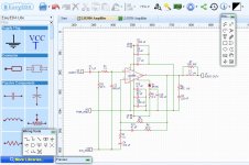
Pin 9 is the inverting input. This pin receives the output signal as feedback. Due to C4 (470uF), the amplifier is only AC coupled meaning that the gain at DC level is 1 (voltage follower) and the voltage at pin 9 should be close to that at the output (pin 3). For an amplifier with negative feedback that works, the signal at the inverting input (pin 9) should follow the signal at the non inverting input (pin 10). Please put your 1KHz signal generator between "SNG_GND" and "AUDIO IN+" and check (with the oscilloscope) that the signal at the "AUDIO IN+" terminal is very similar to the signal at pin 10 of the LM3886. If so, is the signal at pin 9 of the LM3886 also very similar to the signal at pin 10?
OK, close to 7V across R5 (10K) leaves a current of 0.7mA that should be sufficient to un-mute the chip.
Additionally pin 3 shows 0v DC
That is the right DC value.
Pin 8 shows -2.24 for the no good board, with and without a signal in.
Now it is a stable value and we assume the chip is un-muted.
Pin 9 shows -.07 with no signal and -.21 with a signal.
We will need to look at this pin with an oscilloscope.
Comparing the good vs bad, both with a signal, the only pin that is different is pin 9.
Good=0, bad= .21--
So what does pin 9 control ?
Pin 9 is the inverting input. This pin receives the output signal as feedback. Due to C4 (470uF), the amplifier is only AC coupled meaning that the gain at DC level is 1 (voltage follower) and the voltage at pin 9 should be close to that at the output (pin 3). For an amplifier with negative feedback that works, the signal at the inverting input (pin 9) should follow the signal at the non inverting input (pin 10). Please put your 1KHz signal generator between "SNG_GND" and "AUDIO IN+" and check (with the oscilloscope) that the signal at the "AUDIO IN+" terminal is very similar to the signal at pin 10 of the LM3886. If so, is the signal at pin 9 of the LM3886 also very similar to the signal at pin 10?
Last edited:
Resistor 5 shows 25.67 and 18.76. This is the no good board.
OK, close to 7V across R5 (10K) leaves a current of 0.7mA that should be sufficient to un-mute the chip.
Additionally pin 3 shows 0v DC
That is the right DC value.
Pin 8 shows -2.24 for the no good board, with and without a signal in.
Now it is a stable value and we assume the chip is un-muted.
Pin 9 shows -.07 with no signal and -.21 with a signal.
We will need to look at this pin with an oscilloscope.
Comparing the good vs bad, both with a signal, the only pin that is different is pin 9.
Good=0, bad= .21--
So what does pin 9 control ?
Pin 9 is the inverting input. This pin receives the output signal as feedback. Due to C4 (470uF), the amplifier is only AC coupled meaning that the gain at DC level is 1 (voltage follower) and the voltage at pin 9 should be close to that at the output (pin 3). For an amplifier with negative feedback that works, the signal at the inverting input (pin 9) should follow the signal at the non inverting input (pin 10). Please put your 1KHz signal generator between "SNG_GND" and "AUDIO IN+" and check (with the oscilloscope) that the signal at the "AUDIO IN+" terminal is very similar to the signal at pin 10 of the LM3886. If so, is the signal at pin 9 of the LM3886 also very similar to the signal at pin 10?
Ok,here we go.
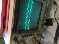
Picture is of pin 10 and AUDIO IN +.
I don't know what you mean by " put your 1Khz signal generator between SIG_GND and AUDIO IN+". From the signal generator, I have the red cable connected to IN+ and the black cable connected to SIG_GND.
Pin 9 is a flat line.
Question: Is there a way to check that the LM3886 is OK?
Thanks
Attachments
Picture is of pin 10 and AUDIO IN +.
I don't know what you mean by " put your 1Khz signal generator between SIG_GND and AUDIO IN+". From the signal generator, I have the red cable connected to IN+ and the black cable connected to SIG_GND.
Exactly what I wanted. We can see the reference signal moving up and down as a sine-wave. As an amplifier is nothing but a high precision servo system, the output voltage should move such that the feedback pin (9) follows the reference pin (10). It doesn't.
Though it is not very likely, the output could be "hanging" (shorted to) on the ground line. This is checked without supply voltage and without load (disconnected). Check with an Ohm-meter from pin 3 to ground that the resistance is more than 100 Ohm.
I have some doubts about the MUTE pin because it does not have a voltage very close to that of the "GOOD" amplifier though the current should be sufficient. I suggest you try the "NO GOOD" amplifier with a resistor of 10KOhm connected directly between pin 8 (MUTE) and the negative supply voltage (-25V). With such a resistor, pin 8 is forced down with good 2mA. If that cannot "wake up" the amplifier, the mute pin is not the problem.
Pin 9 is a flat line.
Yes, pin 9 is actually controlled by the output through the feedback network. Pin 9 should have very close to the same value as pin 3. Without reaction at the output, the chip may be defect.
Does it become hot?
Question: Is there a way to check that the LM3886 is OK?
Yes, but only in a rather trivial sense. Class AB amplifiers do not have diagnosis output pins such as you may find on class D chips. You test if a class AB amplifier is working by putting a voltage or a signal within what is specified in the datasheet on all essential pins and see if the chip does as expected. Hopefully the chips are made with intelligence but they are themselves not intelligent and cannot tell us what is wrong.
Last edited:
Question: Is there a way to check that the LM3886 is OK?
That´s exactly what we are doing.
We apply supply voltages and measure all píns, to check whether we find expected values or not.
Once happy with that, we apply signal and check whether we find expected values or not.
The first one is called Static testing; the second one is Dynamic testing.
We do not know or care what´s inside that literally "black box", we can only check at outside pins.
Even IF we found a bad part "inside", we have no way to replace it.
*Some* packaged amplifiers can be salvaged that way (sometimes) but only because they are real discrete parts amps including a PCB, and a somewhat removable (by hacking) cover (STK or Sanken modules) ..... not the case here.
- Status
- This old topic is closed. If you want to reopen this topic, contact a moderator using the "Report Post" button.
- Home
- Amplifiers
- Chip Amps
- I need help to figure out why this amp doesnt work