With the 10k resistor in place, the voltage at pin 8 is --4.2.
The voltage drop across the 10k resistor is --21.36.
The ohmeter reading between pin 3 and GND is 355k ohms
The chip does not get warm. 😣
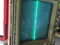
There is still a flat line at pin 3. When I say flat, it is that with a bunch of fuzzy things passing along it.
It's curious that the flat-with-fuzzy scope picture is present even with the power off.
I ordered some things that are supposed to make de-soldering easier.
The voltage drop across the 10k resistor is --21.36.
The ohmeter reading between pin 3 and GND is 355k ohms
The chip does not get warm. 😣
There is still a flat line at pin 3. When I say flat, it is that with a bunch of fuzzy things passing along it.
It's curious that the flat-with-fuzzy scope picture is present even with the power off.
I ordered some things that are supposed to make de-soldering easier.
Attachments
With the 10k resistor in place, the voltage at pin 8 is --4.2.
The voltage drop across the 10k resistor is --21.36.
The ohmeter reading between pin 3 and GND is 355k ohms
The chip does not get warm. ��
There is still a flat line at pin 3. When I say flat, it is that with a bunch of fuzzy things passing along it.
It's curious that the flat-with-fuzzy scope picture is present even with the power off.
I ordered some things that are supposed to make de-soldering easier.
I will just look at the values one more time.
The -4.2V on pin 8 makes sense. 3 diode forward voltage drops of 0.7V each =2.1V total. On top, 1KOhm with good 2mA trough is another 2.1V. 2.1V+2.1V=4.2V. Thus, the LM3886 should be un-muted but the output still doesn't react. Most likely the chip is defect. The output is not hanging on ground.
When I have to remove such a multi-pin IC that is almost certainly defect, I use a pointed wire-cutter and cut each lead individually. Then, I can remove the IC body and following each IC-lead individually. Trying to get 11 leads out in one go is difficult and you risk damaging the PCB copper pads and tracks. Therefore, I de-solder them one-by-one with less risk of damage.
NB: I have just looked through the pin-values you have told me and I cannot see anything other than that LM3886 should have right values to operate from. The chip has most likely turned defect for some reason.
Last edited:
I will just look at the values one more time.
The -4.2V on pin 8 makes sense. 3 diode forward voltage drops of 0.7V each =2.1V total. On top, 1KOhm with good 2mA trough is another 2.1V. 2.1V+2.1V=4.2V. Thus, the LM3886 should be un-muted but the output still doesn't react. Most likely the chip is defect. The output is not hanging on ground.
When I have to remove such a multi-pin IC that is almost certainly defect, I use a pointed wire-cutter and cut each lead individually. Then, I can remove the IC body and following each IC-lead individually. Trying to get 11 leads out in one go is difficult and you risk damaging the PCB copper pads and tracks. Therefore, I de-solder them one-by-one with less risk of damage.
NB: I have just looked through the pin-values you have told me and I cannot see anything other than that LM3886 should have right values to operate from. The chip has most likely turned defect for some reason.
Well, it is the chip that is defective probably due to my poking around reading voltages. Many thanks Faux for the excellent guide in your de-soldering procedure. I was able to remove the LM3886 without damaging the board.
Now on to more curious events.
I put a new LM3886 into the board, applied power and a signal and behold it worked. I did not have a heat sink on so the LM3886 began heating up so I turned off the power.
Now,,,,there is supposed to be a 20k resistor, R4 between pins 3 and 9 and these are the instructions.
"You are supposed to place R4 (20 Ohm) between pins 3 and 9 directly ON the chip.
Good luck,
"
When I did this, the board stopped working and I am guessing that my applying heat to either pins 3 or 9, MESSED UP THE BOARD !
So, I am back to again removing the chip and trying to figure out a better way to solder that resister.
Would someone take a look at the connection of pins 3 and 9 within the chip schematic and see what it says or does or ???
The designer soldered the chip on to the top of the board whereas I was gonna be smart and solder it to the back of the board. maybe that is what's wrong.
If you look closely at the picture you can see where the designer put the resistor, laying on the chip.
Attachments

Now,,,,there is supposed to be a 20k resistor, R4 between pins 3 and 9 and these are the instructions.
"You are supposed to place R4 (20 Ohm) between pins 3 and 9 directly ON the chip.
Good luck,
".
Make sure you use 20K and not 20R. 20R (20 Ohm) will not work.
R4 is the DC feedback resistor and a feedback resistor should be connected close to the chip and with short leads in order to avoid self-oscillation. Directly on the chip leads is exaggerated and very difficult to do in practice. Arranged on the rear side and connected to the right pins should be fine.
I am surprised the designer did not put this essential feedback resistor on the board and next to the chip. That is what other board designers do with LM3886 and it works. Without this resistor, the amplifier will most likely oscillate between the supply rails and certainly not work correctly.
Last edited:
Thank you Faux, you have been especially helpful and have patience in abundance. I have learned a lot of valuable lessons from you.Well done, George.
DIY electronics requires a lot of patience. But, normally you arrive at it working in the end and hopefully the problems you encounter teach you valuable lessons for next time. It has been so for all of us.
Adieu mon ami
- Status
- This old topic is closed. If you want to reopen this topic, contact a moderator using the "Report Post" button.
- Home
- Amplifiers
- Chip Amps
- I need help to figure out why this amp doesnt work