I dunno, I think some people claims the LM3875 sounds better
and it's a bit simpler having no mute circuit. If you've already
got the LM3886s, I say use them.
I used the LM3886 for my initial amplifier, and it sounds quite good even into a difficult load (Acoustic Research AR-11 (four ohms) and Kimber 4TC cable). I chose it because I thought
I'd need the higher power for my speakers. It's wired
exactly according to the data sheets, including RL load
protection on the output.
Because this chassis is modular with the chips wired P2P
and connected via terminal strips all mounted on a heat
sink, I can use my extra heat sinks to build more versions
and I might try it with the LM3875 built to a true GainClone
configuration.
Waiting to see how the LM4780 PCBs turn out, and for
user comments on the sound quality (so far, positive).
I think I'll go that route for my 'finished' amplifier, with
three sets of inputs as I already have a suitable selector
switch in my parts collection.
I've also got something a great many DIYers don't: a
serious audio-oriented test bench and equipment.
No guessing if something's wrong or not.
--Damon
My theory is that the LM3875 is a much simplier chip to implement in a diy design, due to the reduced pin count over the LM3886.
The LM3875 only has 5 pins used: +V, -V, +IN, -IN and OUT.
The LM3886 has 8 pins used: +V, +V, -V, +IN, -IN, OUT, MUTE and GND. (2 +V pins, not a typo)
With the reduced pins, and slightly simplier circuitry (no mute resistor needed), the LM3875 is a simplier implementation, and thus more appealing for a bare minimum components.
As for how the additional mute circuitry effects the sound of the LM3886, I have no idea. I have a pcb design for the LM3886 very similar to the LM3875 design, but I haven't tried it yet.
--
Brian
LM3886- Minimized
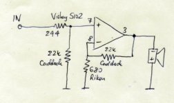
I have tried the LM3886 (schematic here) in a minimal design-- inverting config, and it was stable into speakers and 5 ohm power resistors. That said, I did add to this configuration, more caps (3300 uF per rail total for each of 4 rails) and a differential receiver with its own power supply, though these changes probably don't affect stability. The final result is shown here but put your sunglasses on before clicking the link.
I have tried the LM3886 (schematic here) in a minimal design-- inverting config, and it was stable into speakers and 5 ohm power resistors. That said, I did add to this configuration, more caps (3300 uF per rail total for each of 4 rails) and a differential receiver with its own power supply, though these changes probably don't affect stability. The final result is shown here but put your sunglasses on before clicking the link.
Alcaid said:Have anyone tried the LM3886 with a bare minimum of components, as in the LM3875 minimalist gainclone? (adding one resistor for the mute circuit). Was it stable?
Yes, I did try it and it was absolutely stable. According to Panasonic's table, you can get more power from the 3886 for the same supply.
It sounds great in a minimalistic gainclone. Not surprisingly it was Rowland's choice for his commercial amps.
It's the definitive choice for powering subs, single or in parallel.
Carlos
If you are planning for a sub amp, why don't you check Thomas Madsen's 200 W LM3886 pcb's?rabstg said:So can the 3886 be used with Brian's circuit boards? Could just the chips be swapped?
I am planing a sat sub gainclone and the 3886 would probably be a better choice for the subs if they fit on Brian's PCB's.
Thanks in advance,
Troy
Hi peranders-
I just did a serch on the person's name, LM 3886, and 200 W PCB and didn't get any hits.
Would you by chance have a link or URL?
Also, this is for a desk stereo, a 200 wpc sub "may" be a bit much for the office.
I am building a separate psu to put under the desk and the small amp chassis to put on the desk. Also a pair of line arrays consisting of four 2" speakers and a tweeter(each side) on top and a pair of opposing 6.5" woofers below or 4" TB woofers on top as bases for the line arrays.
Thanks again,
Troy
Edit: Oh yeah, do you know if the LM3886 will work in Brian's PCB's?
rabstg said:
Edit: Oh yeah, do you know if the LM3886 will work in Brian's PCB's?
No! They have different pinout. Read the datasheets.
For a subamp you can use the upcoming group-buy based on the LM4780 chip (boards under development by BrianGT). Read the LM4780 thread in the Chip Amps category.
Datasheet says it will give up to 120W RMS.
120W RMS is only 3dB more than a LM3886 though...
I like LM3886
I like the LM3886. I use it with a large cap on the mute to avoid the turn-on pop associated with AC coupled circuits - tube emulators, and quiet signal switching. The output circuit is inverting and takes in both voltage and current feedback. Additionally, the LM3886 is surrounded by a other circuits to give it tube character. Works great.
Some folks have asked about heatsinking the LM3886 - I use the chassis via a heat spreader. The chassis is .125 aluminum and the heat spreader runs the width to spread the heat better across the width..
I had one that explode!
Was a LM3886, brand new, a friend gave it to me, a good friend, not a bad person that put voltage on pins to invert and destroy the chip.
But it explode, and i check it twice before switch power on, i forgot the protection resistors and also forgot the fuses.
But i checked it once again after explode, and whole conections where perfect, and supply polarity ok!... voltage correct related to applications form, and i check the voltage with 2 voltimeters, i used a heavy gauge wire, the one used to electric water heaters, electric showers.... making 8 ohms exactly, and inductive measure are too low to make it oscilate.
Could not understand, input was shorted to ground with a capacitor, i always do that when first test, and charge resistor where tested and no short.... but lets forget an buy one other.
This explode cost nothing, only the deceptive face of my friend that gave it to me.
Whats the medium cost in US dollares of the LM3885 unit?
Carlos, normally in solid state forum
3886 cost.
Carlos , I think it costs about US$ 5 each.
Try www.digikey.com
and www.newark.com .
If your chip exploded AND your connections are all correct , I can only think that it must be a fake package.
Cheers,
Ashok.
Carlos , I think it costs about US$ 5 each.
Try www.digikey.com
and www.newark.com .
If your chip exploded AND your connections are all correct , I can only think that it must be a fake package.
Cheers,
Ashok.
- Status
- This old topic is closed. If you want to reopen this topic, contact a moderator using the "Report Post" button.
- Home
- Amplifiers
- Chip Amps
- Why is the LM3875 more poular than the LM3886?