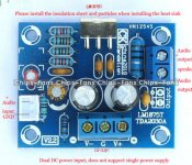
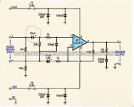
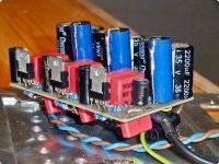
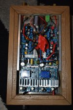
hi ! this has probably been covered many times but new to this !ime experimenting different chip amps trying to find the difference betreen them !!! ime using this pcb but putting better components on , i have read that the input capacitor shown in red should be replaced with a polyester cap but rated at 10uf , whats the best value for this cap ?? also the quoted main capacitors are quoted in the diagram as 220uf but the kit came with 100uf caps , is there a benifit using 100uf over 220uf any helpful responses welcome
Attachments

The lowest voltage 10 uf plastic film cap I was able to find was 63 v. Good luck making that fit. I found some 10 uf aerovox gold COG ceramic film caps on closeout at farnell, which I use as interstage coupler caps in my H182 organ. But farnell US hasn't stocked those in 5 years.
More local rail cap gives a lower frequency full power waveform without clipping. I'm using 560 uf, and 3300 off the board near the bridge rectifier.
I looked at buying one of these boards but all the ones on e-bay were this circuit without the speaker cap. A split supply 24 vac 100 va transformer would be $30 with the UPS fee. I already have several 70 va 24 vac single winding transformers I'd like to use up. It is multitap and goes up to 36 vac but I can't see more than 30 vdc being usable after looking at the current delivery chart. It flattens out at 30.
If find gain of 20 causes clipping at loud volume at the lowest usable setting of my 10 k volume pot. This circuit is gain 22. I tried gain 2 at first but one channel oscillated, as the datasheet says. I'm moving to gain 9.8 now.
Also both channels are motorboating about 3/4 second between pops. As I can't see any input motorboating, I think this might be thermal limiting by the IC. It is a genuine TI IC from farnell US. My heatsink is only 4 cm x 5 cm x 2 cm (each IC) with 5 fins, with a fan on it. These IC's may not be practical if they need a heatsink bigger than will fit in my chassis, I may go to a 5532 op amp driving 4 transistors circuit. DIY Amp Design Critique Chassis is 19" x 5" x 7" Bud. It is possible a Z voltage 0.22 cap (25 v?) is causing the motorboatting by shorting, but I took me 2 days to get 0.22 100 v caps from North Carolina and they didn't arrive until 8 pm yesterday.
Good luck with your project.
Last edited:
You cannot physically fit a polyester 10u cap in place of the electrolytic!
Polyester Film Capacitors | RS Components
You will find no difference in sound reproduction even if you do, apart from the usual "I have spent a fortune so it will sound better".
Polyester Film Capacitors | RS Components
You will find no difference in sound reproduction even if you do, apart from the usual "I have spent a fortune so it will sound better".
You will find no difference in sound reproduction even if you do, apart from the usual "I have spent a fortune so it will sound better".
I have this kit also. What, if any, changes would you suggest?
I would say that 100u caps are OK. It all depends on the stability of your power supply. If you increase the value of the 220u then the will increase the risk of the capacitors holding too much charge for an overload situation, the fuse will blow but the discharge is not fast enough to protect the chip. 100u is what I would use.
To reply to JonesySA, I don't think you can improve the amplifier much except reduce the input capacitance to about 1u to avoid wasting power on subsonic bass.
To reply to JonesySA, I don't think you can improve the amplifier much except reduce the input capacitance to about 1u to avoid wasting power on subsonic bass.
The input cap could be any of the mks2 (or any other mkt) , x7s/r/t ceramic with lead space 5mm or less. Or nichicon es.or kz. Or other ones.... 3uf to 10uf , 25-100v rated. It is no benefit on using 100uf over 220u ,but u will not hear any difference. Those are decoupling caps.
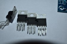
Post a picture of the chips, probability to be fake is high ....
In fact I would save only the resistors and the connectors and trash the caps and the chip.
Post a picture of the chips, probability to be fake is high ....
In fact I would save only the resistors and the connectors and trash the caps and the chip.
I love the LM1875 ") . Same Starter Kit as the Thread Opener, same Ideas. Long story short, expensive higher Quality Parts are not necesarry, they don't bring any Sound Benefits. For the LM1875 it's more important to keep the Traces as short as possible. The 100nF & 100µF Caps should be soldered directly on the Chips Legs. I did what you have in Mind, I've built some circuits with the LM1875 (could've been 30) and I started with 10µF MKP and now I parallel three 680nF X7R and there is no difference.
. Same Starter Kit as the Thread Opener, same Ideas. Long story short, expensive higher Quality Parts are not necesarry, they don't bring any Sound Benefits. For the LM1875 it's more important to keep the Traces as short as possible. The 100nF & 100µF Caps should be soldered directly on the Chips Legs. I did what you have in Mind, I've built some circuits with the LM1875 (could've been 30) and I started with 10µF MKP and now I parallel three 680nF X7R and there is no difference.
The PSU is a Spot where I recognized a positive Effect when I put in the first time "real" Electrolytic Capacitors instead of the few Antiques I found in my Cellar. My LM1875 really liked when I gave him 10000µF or more per rail. Good Grounding is important and if You want to play with the gain, I wouldn't set it too high, because the hum & noise will be amplfied, too. I set it slightly lower then in the Kit with 20 instead of 22k Resistors. If everything else is ok, then there is absolute silence when it's on & there is no Music.
There are circuits for the LM1875 as inverting Amp, as Transconductance Amp, as Composite Amp or as bridged Systm with two Chips. Feel free to find your Favourite.
Best Regards J.
. Same Starter Kit as the Thread Opener, same Ideas. Long story short, expensive higher Quality Parts are not necesarry, they don't bring any Sound Benefits. For the LM1875 it's more important to keep the Traces as short as possible. The 100nF & 100µF Caps should be soldered directly on the Chips Legs. I did what you have in Mind, I've built some circuits with the LM1875 (could've been 30) and I started with 10µF MKP and now I parallel three 680nF X7R and there is no difference. The PSU is a Spot where I recognized a positive Effect when I put in the first time "real" Electrolytic Capacitors instead of the few Antiques I found in my Cellar. My LM1875 really liked when I gave him 10000µF or more per rail. Good Grounding is important and if You want to play with the gain, I wouldn't set it too high, because the hum & noise will be amplfied, too. I set it slightly lower then in the Kit with 20 instead of 22k Resistors. If everything else is ok, then there is absolute silence when it's on & there is no Music.
There are circuits for the LM1875 as inverting Amp, as Transconductance Amp, as Composite Amp or as bridged Systm with two Chips. Feel free to find your Favourite
.Best Regards J.
thanks for replys have now salvaged some poly caps 1.5uf , power suply will be 2x 24v smps ,have done several chip amps so far !to my ears bridged lm3886 sounds best so far ! cant measure distortion ect ! prob not good !!!,,,, any way got 4 of these lm1875 boards, all resistors have been precision matched and will prob bridging them too !I love the LM1875
The PSU is a Spot where I recognized a positive Effect when I put in the first time "real" Electrolytic Capacitors instead of the few Antiques I found in my Cellar. My LM1875 really liked when I gave him 10000µF or more per rail. Good Grounding is important and if You want to play with the gain, I wouldn't set it too high, because the hum & noise will be amplfied, too. I set it slightly lower then in the Kit with 20 instead of 22k Resistors. If everything else is ok, then there is absolute silence when it's on & there is no Music.
There are circuits for the LM1875 as inverting Amp, as Transconductance Amp, as Composite Amp or as bridged Systm with two Chips. Feel free to find your Favourite
Best Regards J.
Attachments
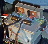
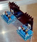
Seems the Server couldn't handle as much Pics/ MB's as I had marked to upload. Now they come in smaller numbers.
The Pics are chronological and start, as you maybe guess, with "china blue". And I really had no Clue in what I was stumbling in as I put this Thing together ... .
The Pics are chronological and start, as you maybe guess, with "china blue". And I really had no Clue in what I was stumbling in as I put this Thing together ... .
Attachments
Last edited:
As said you can use 1uF instead of the 10uF+. No problem.
But I would use 2.2uF polyester of the MKT grade.
As said also the 100uF+ caps are no problem. They are not much different from 220uF+
I congratulate you to the LM1875 amplifier.
We can hardly get better for so good price.
But I would use 2.2uF polyester of the MKT grade.
As said also the 100uF+ caps are no problem. They are not much different from 220uF+
I congratulate you to the LM1875 amplifier.
We can hardly get better for so good price.
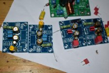
thanks for all the responses , finally finished amp and decided on the parallel option , tried the standard pair of lm1875 boards but found that deep bass notes made cracking noises through speakers when the volume was turned up , so increased board capacitors thinking this may help,any way sounds great now and more authoritive,( too my ear )the lm1875 sounds more organic than the lm3886
Attachments
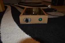
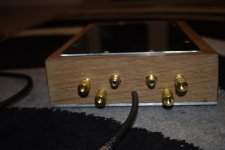
thanks for all the responses , finally finished amp and decided on the parallel option , tried the standard pair of lm1875 boards but found that deep bass notes made cracking noises through speakers when the volume was turned up , so increased board capacitors thinking this may help,any way sounds great now and more authoritive,( too my ear )the lm1875 sounds more organic than the lm3886
I made an LM1875 amplifier with chips looking pretty much like yours and I observed a phenomenon that could be heard as "cracking noises". With supply voltages above +/-24V in an 8 Ohm load, the LM1875 would start spurious self-oscillations when the output level got high. Such self-oscillation made a part of the sine-wave collapse. With a 4 Ohm load, the phenomenon started around +/-18V.
What supply voltage and speaker impedance do you use?
If you have more LM1875 chips working in parallel it may influence the level at which such self-oscillation starts.
hi the speakers are 6ohm me thinks ! q acoustics 3020 but had similar effects with my test speakers as well ! power supply is 24v ! but in parallel no such problems
- Status
- This old topic is closed. If you want to reopen this topic, contact a moderator using the "Report Post" button.
- Home
- Amplifiers
- Chip Amps
- lm1875