Before I start on my first chip amp project using the higher end boards on my workbench, I want to start by building out a few of the lower end single channel LM386, LM1875, and TDA2050 based boards I have. Some of the schematics/boards show an electrolytic cap in the signal path between the input positive and the op amp. I am confused about using a polarized cap in this application. Some research shows them used in some circuits but I have seen the polarity either way. Other diagrams show no polarity I guess to indicate a BP cap or it doesn't matter. Some suggest that this is not proper design, others say it's OK because the small voltages of a preamp signal can be reversed through an EL cap.
First, how do I select the polarity. especially if there is no DC biasing level, to use what I have? Second, what is best practice?
BTW, the first board I started building shows it one way on the schematic and the opposite on the board.
Thanks,
George
First, how do I select the polarity. especially if there is no DC biasing level, to use what I have? Second, what is best practice?
BTW, the first board I started building shows it one way on the schematic and the opposite on the board.
Thanks,
George
Before I start on my first chip amp project using the higher end boards on my workbench, I want to start by building out a few of the lower end single channel LM386, LM1875, and TDA2050 based boards I have.
CLEVER IDEA! I see noobs starting with multichannel LM3886s. The risk they end up in trouble is high. Start with something simple and learn your basic lessons there.
Some of the schematics/boards show an electrolytic cap in the signal path between the input positive and the op amp. I am confused about using a polarized cap in this application. Some research shows them used in some circuits but I have seen the polarity either way. Other diagrams show no polarity I guess to indicate a BP cap or it doesn't matter. Some suggest that this is not proper design, others say it's OK because the small voltages of a preamp signal can be reversed through an EL cap.
In practice you have to figure out how the dc voltages at the two capacitor terminals are in idle mode. Then you turn the capacitor to match this polarity.
First, how do I select the polarity. especially if there is no DC biasing level, to use what I have? Second, what is best practice?
If you have about the same potential at both ends of an electrolytic capacitor, you turn it either way and use the effect that an electrolytic capacitor can be biased with around 1V the "wrong way" without damage. Better is to use a bi-polar (non polarized) audio capacitor, in particular if it is in the signal path. Such are not particularly expensive.
BTW, the first board I started building shows it one way on the schematic and the opposite on the board.
Can you please post a scan?
Thanks,
No trouble
NB: Also I use Nichicon bi-polar capacitors.
Last edited:
First, how do I select the polarity. especially if there is no DC biasing level, to use what I have? Second, what is best practice?
There will always be a small DC offset across the capacitor. You can figure this out from the direction of the input bias current of the chipamp. The DC offset tends to be small (a few mV), thus you don't have to worry too much about the polarization. That said, I usually try to set up the circuit such that the polarity of the DC offset on a cap is lined up with the polarity of the cap.
If the DC offset worries you, use a non-polarized cap. Either a bipolar or a film cap.
Tom
Before I start on my first chip amp project using the higher end boards on my workbench, I want to start by building out a few of the lower end single channel LM386, LM1875, and TDA2050 based boards I have.
CLEVER IDEA! I see noobs starting with multichannel LM3886s. The risk they end up in trouble is high. Start with something simple and learn your basic lessons there.
Some of the schematics/boards show an electrolytic cap in the signal path between the input positive and the op amp. I am confused about using a polarized cap in this application. Some research shows them used in some circuits but I have seen the polarity either way. Other diagrams show no polarity I guess to indicate a BP cap or it doesn't matter. Some suggest that this is not proper design, others say it's OK because the small voltages of a preamp signal can be reversed through an EL cap.
In practice you have to figure out how the dc voltages at the two capacitor terminals are in idle mode. Then you turn the capacitor to match this polarity.
First, how do I select the polarity. especially if there is no DC biasing level, to use what I have? Second, what is best practice?
If you have about the same potential at both ends of an electrolytic capacitor, you turn it either way and use the effect that an electrolytic capacitor can be biased with around 1V the "wrong way" without damage. Better is to use a bi-polar (non polarized) audio capacitor, in particular if it is in the signal path. Such are not particularly expensive.
BTW, the first board I started building shows it one way on the schematic and the opposite on the board.
Can you please post a scan?
Thanks,
No trouble
NB: Also I use Nichicon bi-polar capacitors.
Here is the first one:
George
Attachments
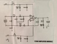
> Here is the first one:
LM1875 input bias current is nominally cancelled to within +/-2uA.
2uA in 22k resistor is 44mV.
Additional +/-15mV input offset error.
You could have 0.059mV of DC on the chip input (and you can't know which polarity).
0.06V is much less than the ~~1V which a Polar electro will stand "forever" without ill effect. Slap it together any which way and enjoy.
When more voltage is expected, you can often build without caps, probe the two cap pads with your meter, and determine which-way and how-much DC is present. This will sometimes "fail" because the lack of connection may allow oscillation, but for small amps it is always worth a try.
> Here is the first one:
LM1875 input bias current is nominally cancelled to within +/-2uA.
2uA in 22k resistor is 44mV.
Additional +/-15mV input offset error.
You could have 0.059mV of DC on the chip input (and you can't know which polarity).
0.06V is much less than the ~~1V which a Polar electro will stand "forever" without ill effect. Slap it together any which way and enjoy.
When more voltage is expected, you can often build without caps, probe the two cap pads with your meter, and determine which-way and how-much DC is present. This will sometimes "fail" because the lack of connection may allow oscillation, but for small amps it is always worth a try.
Good explanation, thank you,
George
I try not use electrolytics on audio signals if possible.
I try to keep input impedance high and use a 470nF poly.
If its an amp I would put the + end of the cap to the pre amp as some pre amps use single rail supplies meaning output is at half b+.
I did an experiment with a 10uF electrolytic and found it will work ok up to 1.5 volts dc reverse biased.
I got caught out with a power amp feedback network which had a 10uf to ground.
The amp dc offset was quite a bit negative and this made the 10uf reverse biased.
The problem with this is the amp then has dc gain amplified as much as ac and cause instability.
So now I use two 22uf's back to back to get rid of the problem.
Last edited:
where is the correct place to put a volume control in the circuit in post #5?
At the audio signal input, before the coupling capacitor.
Last edited:
- Status
- This old topic is closed. If you want to reopen this topic, contact a moderator using the "Report Post" button.
- Home
- Amplifiers
- Chip Amps
- Electrolytic capacitor polarity in the signal path