During the build I will post some updates in this topic, while I will use the first posts as a information collection.
Somewhere in 2008 I build my first LM3886 amplifier based on a GrianGT (Chipamp.com) kit driving two home-build Visaton Aria Light speakers: ARIA 2 LIGHT | Visaton. Later a Chinese Ebay PCM1974A 24bit/192kHz DAC was added (separate enclosure). That set-up is running fine since 2008. Recently I build another amp: https://www.diyaudio.com/community/threads/lm3886dr-dac-build.380135/
For now I will keep using the Visaton Aria Light speakers, but a set of Visaton Concorde MK3 is in the making (hope I can finish those somewhere halfway 2022).
==========================================
Enclosure
Ebay / AliExpress - search: YA43 Aluminium Amplifier Enclosure
Layout sketch
"Dirty" AC on the left
"Clean" audio on the right
Each LM3886 will have its own 200*100*50mm heatsink
==========================================
DAC
https://github.com/iancanada/DocumentDownload
-RecieverPi (for optical signal input)
-FifoPi reclocker
-Dual Mono ES9038Q2M DAC HAT, with LT3042 low noise regulator PCB's
-I/V STD standard OPA I/V stage with Balanced outputs, with OPA1612 op-amp upgrade --> Balanced output is about 4V RMS
Status:
-IanCanada boards received
-LT3042 regulator parts to be ordered
-OPA1612 opamps to be ordered
Attenuator:
Khozmo Stepped attenuator - Series type - 10kOhm
Information on line levels / potentiometers:
https://en.wikipedia.org/wiki/Line_level
https://www.audioholics.com/audio-amplifier/amplifier-voltage-gain
Help in choosing a potentiometer as a "Passive preamplifier"
==========================================
Power Supply
Inrush limiter(s)
-Sjöström Adio - SST03: https://sjostromaudio.net/cart/gb/mains-circuits/10-sst03-softstart-for-toroidal-transformers.html
Status: PCB received, all parts on stock
DC Filter
http://sjostromaudio.com/pages/index.php/hifi-projects/109-dct02-the-dc-trap-high-end-style?start=1
Background information
https://www.diyaudio.com/forums/pow...zzing-toroid-transformers-14.html#post4302237
http://sound.whsites.net/articles/xfmr-dc.htm
--> DCT-02 would do the job for me, but I needed a solution to give each toroid its own fuse. The cabinet did not have that much space left anymore, so I installed Eagle again and build a DC trap with 4 individual outputs, each with is own fuse. Boards are ordered (10-FEB-2021), lets see how it works out.
Status:
-PCB designed, ordered and received
-All parts on stock
Toroidal Transformers
-1x Amplimo 2x22VAC @ 160VA for Modulus-86 (left channel)
-1x Amplimo 2x22VAC @ 160VA for Modulus 86 (right channel)
-1x Amplimo 2x07VAC @ 15VA for the IAN Canada DAC FiFoPi + DAC
-1x Amplimo 2x12VAC @ 15VA for the IAN Canada IV stage
Status: 22VAC toroid on stock, 07VAC and 12VAC toroids to be ordered + check what voltage would be best with the ultrabibs.
PSU's
1x Power-686 from Neurochrome (left channel) --> status: boards + parts on stock
1x Power-686 from Neurochrome (right channel) --> status: boards + parts on stock
1x ?????? +5V (for reclocker)
1x ?????? +5V (for DAC)
1x Salas SSLV1.3 UltraBiB for +12V (Ian Canada DAC I/V stage) --> boards on stock, parts to be ordered
1x Salas SSLV1.3 UltraBiB for -12V (Ian Canada DAC I/V stage) ---> boards on stock, parts to be ordered
Notes for the Salas Ultrabib regulators
https://www.diyaudio.com/forums/pow...ultrabib-shunt-regulator-171.html#post5895950
https://www.diyaudio.com/forums/pow...ultrabib-shunt-regulator-101.html#post5659907
https://www.diyaudio.com/forums/pow...ultrabib-shunt-regulator-101.html#post5659688
https://www.diyaudio.com/forums/pow...ultrabib-shunt-regulator-101.html#post5659649
https://www.diyaudio.com/forums/pow...ultrabib-shunt-regulator-101.html#post5659625
Salas SSLV1.3 UltraBiB shunt regulator
Salas line rejection, output noise and impedance comparison: https://diyaudiostore.com/collections/power-supplies-accessories/products/super-regulator (performance graphs)
Notes for the Neurochrome Power-686 boards
-Standard caps are 35*50mm and have two pins at a 10.16mm grid
-The PCB and enclosure allow caps up to 40*85
-This allows some "freedom" to select other capacitors, focusing on diameter/height, temperature, lifetime, ESR and Ripple current specs.
-After some research conclusion: yes, better caps are available, at least, you will find them in datasheets, but availability on consumer level is another issue.
-Long story short, the capacitors in the standard Neurochrome Bill of Materials are one of the best (if not the best) you will find.
--> Update 29-SEP-2019: I managed to get my hands on a set of Cornell Dubilier 380LX333M050A082 (33.000uF / 50V) capacitors. "There is no such thing as overdoing it"
Sources / information:
Toroid leakage article: http://engineering.nyu.edu/power/sites/engineering.nyu.edu.power/files/uploads/leakage 2.pdf
==========================================
LM3886 - Neurochrome Modulus-86 Rev. 2.3
https://www.neurochrome.com/modulus-86/
Gain / output power
DAC output: 4.0V RMS
Mod-86 input sensitivity with THAT1200: 1.8V RMS
Mod-86 input sensitivity with THAT1206: 3.6V RMS
Best way to go is the THAT1206 driver and maybe add a 1,1 kOhm resistor prior to the attenuator to mitigate the 0.4V (10%) difference
Power dissipation:
TI advice is to stay below 40W. Looking at the voltage levels and speaker impedance, I will calculate with 50W, to be on the very very safe side. However, it is more likely to have complaining neighbours before reaching maximum power output. Each amp will have one 200*100*50mm heatsink. Sadly, the Chinese heatsink comes without a datasheet, so we have to make an educated guess on the thermal resistance. A comparable heatsinks will have 0.7K/W (Fisher SK47 200*100*40).
Tjunction max = 150C
Tambient = 25C
Pdiss = 50W
Heatsink = 0.7K/W (estimation)
LM3886 = 1.0K/W (TF version = 2.0K/W)
Keratherm pad = 0.1K/W
For just one LM3886, calculated with a worst, worst case scenario:
Tjunction = Tambient + Pdiss * (θLM3886 + θKeratherm pad + θHeatsink) → Tjunction = 25 + 50 * (1.0 + 0.1 + 0.7) = 115 °C.
The heatsink itself will be 25C + θHeatsink*Pdiss = 25+0.7*50 = 60C
Information source:
https://www.neurochrome.com/taming-the-lm3886-chip-amplifier/thermal-design/
http://www.ti.com/lit/ds/symlink/lm3886.pdf
==========================================
Miscellaneous:
Speaker Protection
In 10 years time I never suffered a failed amplifier, luckily. Less parts in the audio path always seemed better to me. Especially relays with mechanical contacts that can get dirty over time. But while surfing around the Neurochrome website I saw the Guardian-86: compact, clean, simple, solid state and above all: no measurable distortion. Basically taking away all my arguments not to it....
Solder
-Standard 60/40 (tin/lead) solder with resin core for the power circuits
Wiring
-230VAC wiring: Lapp, 1mm^2 Orange, type: ÖLFLEX® HEAT 180 SIF (tinned copper, better corrosion protection)
-DC wiring: Lapp, 4mm^2 Black/Red, type: ÖLFLEX® HEAT 180 SIF (tinned copper, better corrosion protection)
-Signal cables: Microphone cable, OFC copper, 65pF/m, carbon+copper shielded
Binding Posts
-Ordered from Neurochrome
Mains Switch:
Replaced the Chinese mains switch (that came with the Chassis) with: PWL-2P1TL-6SASHA (230VAC / 6A rating)
PCB maker
https://jlcpcb.com
https://www.itead.cc/open-pcb.html
Last edited:
In Sketchup I made some 3D sketches for the enclosure layout. A few sketches and failed ideas later only two viable options where left:
A. Toroids stacked vertically in the front.
B. Toroids bolted to the side.
What are your thoughts on these designs?
Option A is the easiest to build, everything can be bolted or stacked to a flat surface. However, the lay-out looks a little messy and will be harder to keep a decent seperation between the AC and DC parts.
Option B is more complicated to build. I will have to do create supports/holders for the toroids on my 3D printer, since I can't hang all the weight on the side wall. Also I do not want to bolt trough the side wall.... The big plus: better separation of AC and DC. It will probably give the "cleanest" inside wiring.
A. Toroids stacked vertically in the front.
B. Toroids bolted to the side.
What are your thoughts on these designs?
Option A is the easiest to build, everything can be bolted or stacked to a flat surface. However, the lay-out looks a little messy and will be harder to keep a decent seperation between the AC and DC parts.
An externally hosted image should be here but it was not working when we last tested it.
An externally hosted image should be here but it was not working when we last tested it.
Option B is more complicated to build. I will have to do create supports/holders for the toroids on my 3D printer, since I can't hang all the weight on the side wall. Also I do not want to bolt trough the side wall.... The big plus: better separation of AC and DC. It will probably give the "cleanest" inside wiring.
An externally hosted image should be here but it was not working when we last tested it.
An externally hosted image should be here but it was not working when we last tested it.
Hi PKO,
Do you have a reason for choosing such a small chassis? The transformers are pretty close to the signal so if you find you're getting magnetic interference you won't be left with many options. I think that will have a far greater impact than choice of caps / wire / op amps. I struggled with interference in a pre-amp with much more space and smaller transformers here.
You might also want to think about using the differential outputs / inputs of the dac and modulus boards (although that would require a four pole attenuator).
Hope that's useful.
Simon.
Edit: Also I've just noticed that you have both amplifier boards sharing the same section of heatsink, to use that heatsink properly they need to be side by side.
Last edited:
I'm telling you this as a retired wiring technician...that layout is big trouble. That's a LOT of stuff crowded into the available space...I strongly suggest a significantly larger case or don't try to put it all in that one single case, maybe a second one for the digital stuff? You are going to have possible thermal issues, mutual interference between modules and their radiated fields, and the one it seems nobody considers until it's too late...THE WIRES! The wiring for all that stuff is going to consume more of the available space than you'll realize, and crowding them together can lead to cross-coupling of digital-analog-power signals.
Oh yeah...if you do ending up doing it that way and there are problems, to do any trouble shooting in that layout will be a NIGHTMARE.
Mike
Oh yeah...if you do ending up doing it that way and there are problems, to do any trouble shooting in that layout will be a NIGHTMARE.
Mike
Last edited:
simonra and Michael Bean,
Thank you for your input and feedback, well appreciated")
Reason/History for the small chassis:
The original plan was to build a new amplifier based the GrianGT Chipamp.com kit. Those boards are very compact, making this enclosure large enough (in my opinion). No speaker protector boards where taken in account, even freeing up even more space. The chassis already arrived at the moment Chipamp.com went out of business. The chassis is collecting dust since 2016. If reasonably possible, I would like to put the chassis to good use again. If not, I will have to order a new one.
Differential signals:
Good one! The Modulus-86 boards are build for differential, that is a good start. This version of the DAC standard has unbalanced RCA outputs. Looking the (amount+type of) opamps I should be able to pull a differential signal from the board somewhere. To be continued . This will require some reverse engineering, since no electrical drawings are available.
Thermal Design:
Thermal calculation(s) to be made. The original idea of stacking the boards this way was to place the DAC and stepped attenuator in between, minimizing signal path lengths. Having enough power dissipation is not the first worry. More concerning is that the top amp will most likely get hotter than the bottom one (hot air flows up), creating a possible risk of inequality between the amps. I will try to shuffle it around a little, tilting both LM3886 boards by 90 degrees and see how that works out for the lay-out. To be continued
Wiring:
Actually I was not to worried about this part, however I do understand you get worried at first sight. Yes, it will be crowded. Yes, it is (very) easy to mess up. Putting everything together directly, switch it on and then start troubleshooting with only the top lid open, YES, that will be one hell of a job. I totally agree on that one. Aim is to test as much as possible "on the table" before putting all together.
One advantage of this chassis is each side, front, back top, bottom panel and heatsink can be taken out individually. With just a few screws the heatsink with the LM3886, DAC and attenuator is out, giving "free" access to them.
Interference / Radiation
To be honest, I am still looking for a good book/source. Reading trough DIYaudio forums I see (a lot of) of different claims/views/opinions. Ranging from "keep having troubles" to "I placed a toroid just 2 inches from the amp and no hum at all". The topics are very interesting to read.
For magnetic shielding MuMetal seems to be the best option
For EMI/RFI shielding I see different solutions, ranging from tin cans to heavy iron plates, copper foil or aluminum sheets
Yesterday I received a message from DHL: the DAC should arrive Wednesday. That allows me to check what voltage regulators are used, check the datasheets and see if it is really needed to use a 15-0-15VAC transformer or I can use a 12-0-12VAC one (lowering heat dissipation).
Thank you for your input and feedback, well appreciated
Reason/History for the small chassis:
The original plan was to build a new amplifier based the GrianGT Chipamp.com kit. Those boards are very compact, making this enclosure large enough (in my opinion). No speaker protector boards where taken in account, even freeing up even more space. The chassis already arrived at the moment Chipamp.com went out of business. The chassis is collecting dust since 2016. If reasonably possible, I would like to put the chassis to good use again. If not, I will have to order a new one.
Differential signals:
Good one! The Modulus-86 boards are build for differential, that is a good start. This version of the DAC standard has unbalanced RCA outputs. Looking the (amount+type of) opamps I should be able to pull a differential signal from the board somewhere. To be continued
. This will require some reverse engineering, since no electrical drawings are available.Thermal Design:
Thermal calculation(s) to be made. The original idea of stacking the boards this way was to place the DAC and stepped attenuator in between, minimizing signal path lengths. Having enough power dissipation is not the first worry. More concerning is that the top amp will most likely get hotter than the bottom one (hot air flows up), creating a possible risk of inequality between the amps. I will try to shuffle it around a little, tilting both LM3886 boards by 90 degrees and see how that works out for the lay-out. To be continued
Wiring:
Actually I was not to worried about this part, however I do understand you get worried at first sight. Yes, it will be crowded. Yes, it is (very) easy to mess up. Putting everything together directly, switch it on and then start troubleshooting with only the top lid open, YES, that will be one hell of a job. I totally agree on that one. Aim is to test as much as possible "on the table" before putting all together.
One advantage of this chassis is each side, front, back top, bottom panel and heatsink can be taken out individually. With just a few screws the heatsink with the LM3886, DAC and attenuator is out, giving "free" access to them.
Interference / Radiation
To be honest, I am still looking for a good book/source. Reading trough DIYaudio forums I see (a lot of) of different claims/views/opinions. Ranging from "keep having troubles" to "I placed a toroid just 2 inches from the amp and no hum at all". The topics are very interesting to read.
For magnetic shielding MuMetal seems to be the best option
For EMI/RFI shielding I see different solutions, ranging from tin cans to heavy iron plates, copper foil or aluminum sheets
Yesterday I received a message from DHL: the DAC should arrive Wednesday. That allows me to check what voltage regulators are used, check the datasheets and see if it is really needed to use a 15-0-15VAC transformer or I can use a 12-0-12VAC one (lowering heat dissipation).
If you have the chassis already then there's no harm in trying to use it... just be aware of the difficult task you've set yourself. If you go with your layout then you'll need a 'plan b' to put the power supply in a different box if/when you get problems.
I'd guess that the heatsink you have is about the right size (it's worth doing the calculations) but you need to use all of it, in the layout half of it isn't cooling anything. I'd also say that within reason you don't really need to worry about the length of the signal path between the boards... where the path length does matter tomchr has done the hard work for you with the design of the modulus. Inadequate cooling will have a far greater impact than 15cm of wire.
With regard to interference from the power supply components, the starting point is placement within the chassis and that's difficult (impossible?) to optimise without experimenting and for that you need space to move them around. Although you are right to start by looking at best practice.
In my limited experience it's always been my own self imposed constraints (case size, aesthetics etc) that have caused the biggest headaches and it's satisfying when you make it work but frustrating if you always know you could have made it better... but then I guess that's what makes this addictive.
Updates:
Neurochrome
The order is placed!
2x Power-686 - Unpopulated Board
2x Modulus-86 - Unpopulated Board
2x Guardian-86 - Unpopulated Board
2x Output inductor
2x Binding Posts
1x set of Keratherm pads
Chassis
"If it don't fit, use a bigger hammer". Well...., I was running out of hammers trying to fit it in the small enclosure . Trading one problem for another in an endless circle. The only way it could fit+work was buying new toroidal transformers with a lower voltage. A lower supply voltage reduces maximum heat dissipation (see figure 35 and 36 of the datasheet), also lowering maximum output power. Lower output power, temperatures still on the absolute limit and buying two new transformers isn't cheap either, for that money I rather buy a larger enclosure.
Modushop is a good option. Since it is inside Europe, I do not have to pay additional import fees. The Dissipante 2U or 3U would be good options. The 2U 400mm deep full aluminum version costs +- 205,- EUR, shipping included.
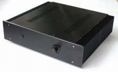
The other option is a Chinese / Ebay / Alibaba enclosure. The model displayed below can be found on Ebay and AliExpress when you search for "Chassis YA43". With the current conversion rate it costs around 135,- euro's shipping included. With import duties it will be round 180,- euro's total. Volume knob, power socket, switch are included and some holes are already pre-drilled in the back panel. How much easier can it be? It offers enough space on the inside (W=365mm, H=103mm, D=400mm).
Plan: Toroids on the left, PSU boards in the middle, audio on the right side. Each LM3886 will have its own 200*100*50mm heatsink. 3D drawing/lay-out to come.
Neurochrome
The order is placed!
2x Power-686 - Unpopulated Board
2x Modulus-86 - Unpopulated Board
2x Guardian-86 - Unpopulated Board
2x Output inductor
2x Binding Posts
1x set of Keratherm pads
Chassis
"If it don't fit, use a bigger hammer". Well...., I was running out of hammers trying to fit it in the small enclosure
. Trading one problem for another in an endless circle. The only way it could fit+work was buying new toroidal transformers with a lower voltage. A lower supply voltage reduces maximum heat dissipation (see figure 35 and 36 of the datasheet), also lowering maximum output power. Lower output power, temperatures still on the absolute limit and buying two new transformers isn't cheap either, for that money I rather buy a larger enclosure.Modushop is a good option. Since it is inside Europe, I do not have to pay additional import fees. The Dissipante 2U or 3U would be good options. The 2U 400mm deep full aluminum version costs +- 205,- EUR, shipping included.
The other option is a Chinese / Ebay / Alibaba enclosure. The model displayed below can be found on Ebay and AliExpress when you search for "Chassis YA43". With the current conversion rate it costs around 135,- euro's shipping included. With import duties it will be round 180,- euro's total. Volume knob, power socket, switch are included and some holes are already pre-drilled in the back panel. How much easier can it be? It offers enough space on the inside (W=365mm, H=103mm, D=400mm).
Plan: Toroids on the left, PSU boards in the middle, audio on the right side. Each LM3886 will have its own 200*100*50mm heatsink. 3D drawing/lay-out to come.
Attachments
Good news: the DAC arrived early
Bad news: it has the wrong DAC chip mounted (PCM1798), despite being clearly listed as PCM1794.
The seller offers both versions, so hopefully it is just a small mistake. If not, I will have to deal with the lesser PCM1798 version of the board OR find an entirely other DAC board (with the PCM1798).
In the mean time I will keep looking for other viable alternatives, just in case.
Updates:
Neurochrome
The order is placed!
2x Power-686 - Unpopulated Board
2x Modulus-86 - Unpopulated Board
2x Guardian-86 - Unpopulated Board
2x Output inductor
2x Binding Posts
1x set of Keratherm pads
Chassis
"If it don't fit, use a bigger hammer". Well...., I was running out of hammers trying to fit it in the small enclosure
Modushop is a good option. Since it is inside Europe, I do not have to pay additional import fees. The Dissipante 2U or 3U would be good options. The 2U 400mm deep full aluminum version costs +- 205,- EUR, shipping included.
The other option is a Chinese / Ebay / Alibaba enclosure. The model displayed below can be found on Ebay and AliExpress when you search for "Chassis YA43". With the current conversion rate it costs around 135,- euro's shipping included. With import duties it will be round 180,- euro's total. Volume knob, power socket, switch are included and some holes are already pre-drilled in the back panel. How much easier can it be? It offers enough space on the inside (W=365mm, H=103mm, D=400mm).
Plan: Toroids on the left, PSU boards in the middle, audio on the right side. Each LM3886 will have its own 200*100*50mm heatsink. 3D drawing/lay-out to come.
Consider putting the PSU components in their own chassis. Then you can use the chassis you originally have for the amplifier. I would strongly recommend keeping the power. Components (especially the transformer) well away from your signal path. I really like your BOM, this is going to be a great amplifier!
DAC
The supplier shipped a new DAC, hopefully the correct one this time. The package should arrive this week. Luckily no issues, he was very helpful and quick to respond.
Soekris DAM1021
I also found the Soekris DAM1021 R-2R DAC on the forum. Interesting to read about (and there is a lot to read!). For now I will continue with the PCM1794 based DAC, but keep some space free for possible future plans. I added some information / reference / links regarding Soekris to the the startpost.
Neurochrome
The PCB's have been shipped, should arrive in a few weeks. I still have to order the parts for the boards. The next 2-3 weeks will be very busy, so I do not expect much progress till the end of next month.
DC blocker
The original plan was to DIY a schematic/PCB in Eagle or do it the dirty way on a prototyping board. Yesterday I found the Sjöstrom Audio DCT02/03 DC Blocker. Exactly what I want! That saves a lot of time.
Chassis
This subject start to get more and more interesting. Thanks for the input. I gave the dual / split chassis a tough, but I do not think it will be the best way for this project. If anyone has a different point of view: please share your input.
Splitting the chassis, gives me two options:
CH1: Toroids + Power-686 boards
CH2: Mod-86 + DAC + stepped attenuator
Connectors + Cables will add extra resistance between the capacitors and the LM3886, basically throwing away the benefits of two parallel connected low ESR (13mOhm) capacitors.
OR
CH1: Toroids
CH2: Power-686 + Mod-86 + DAC + stepped attenuator
Downside: once again, AC near the audio parts
Cost perspective: ordering one extra chassis and a bunch of good connectors + cables for the connections will as costly as one new "large" chassis (YA43).
The only gain will be somewhat more distance between the toroids and the audio equipment (75, max 100mm extra estimated, I do not have much space to place the two chassis far apart) and some 6 millimeters of extra aluminium in between. Is it worth the hassle and disadvantages? I do not think so. I'd rather use one (large) YA43 chassis and add a decent shield/divider to it. At the moment I am reading about how to properly shield toroids. If anyone has a good source, it would be very welcome.
Good suggestion to let Tom from Neurochrome know. I will send him an e-mail soon to check his input and opinion.
Consider putting the PSU components in their own chassis.
That's actually not such a hot idea in a power amp. Putting the supply separate maximizes the supply impedance. It also maximizes the coupling from the supply wiring into the the rest of the circuit and audio system. A Class AB output stage draws current in pulses. The positive supply supplies the output current during the positive swing of the output and the negative supply supplies the current for the negative swing. This, combined with the relatively high output current, makes the supply wiring the perfect radiator/antenna for coupling into sensitive circuitry, such as audio amps. This results in rail-induced distortion. Douglas Self writes about this in his Power Amp Design Handbook.
Rather, I recommend putting everything into one chassis and minimizing the wire lengths to the power supply and power transformer.
Tom
Once you get there, I would very much welcome your build pictures and build experience in the Modulus-86 Build Thread: Modulus-86 build thread
Tom
Tom
That's actually not such a hot idea in a power amp. Putting the supply separate maximizes the supply impedance. It also maximizes the coupling from the supply wiring into the the rest of the circuit and audio system. A Class AB output stage draws current in pulses. The positive supply supplies the output current during the positive swing of the output and the negative supply supplies the current for the negative swing. This, combined with the relatively high output current, makes the supply wiring the perfect radiator/antenna for coupling into sensitive circuitry, such as audio amps. This results in rail-induced distortion. Douglas Self writes about this in his Power Amp Design Handbook.
Rather, I recommend putting everything into one chassis and minimizing the wire lengths to the power supply and power transformer.
Tom
Increasing the length of a conductor doesn't "maximize" impedance. If we're talking about RF here, which it sounds like, then the impedance is a complex function of the wire geometry. I'll admit the DC resistance is increased. Regardless, having a higher impedance does not necessarily make the device a better RF radiator. That is an oversimplification. Assuming each rail carries the current for each half cycle, you can treat this as half wave rectification. Assuming the highest frequency you'll amplify is 20kHz, then the second harmonic is 40kHz. The quarter wavelength of 40kHz is well over a kilometre. If the interconnection is 1 meter or 10 centimetres they are both electrically too short to be effective radiators at 40kHz. If we're not talking about RF, but instead stray inductance, then keep in mind proximity plays just as big of a role as the inductance itself.
Everything is a tradeoff, by moving the power components into a separate chassis you may reduce inductive coupling while degrading the so called rail distortion performance. I was not stating that a separate chassis is superior, simply an alternative. I gave the book you referenced a cursory read, I could not find a statement that recommend against a separate chassis for the power supply components. If the amplifier is sensitive to the resistance of the supply, I would suggest that if a separate chassis was used, that the gauge of the supply line be sized correctly. Anyway I'll show myself out, since this is a bit off topic.
Thanks,
PSU's
1x Power-686 from Neurochrome (left channel)
1x Power-686 from Neurochrome (right channel)
Just curious, why Power-686 and why 2 of them? AFAIK 2xModulus86 as you have can be powered from a single Power-86, no need for bigger PSU. Maybe I'm missing something.
Increasing the length of a conductor doesn't "maximize" impedance.
Over-simplification, I agree.
Long wire -> higher DCR, higher series inductance -> higher impedance. At least with short wires at LF where the capacitance between conductors can be neglected.
You're also right about the antenna. The coupling mechanism for rail-induced distortion is inductive coupling through the mutual inductance between the supply harness and everything else. The antenna analogy makes it easier to understand and I like the analogy even if it isn't 100% technically accurate.
I gave the book you referenced a cursory read, I could not find a statement that recommend against a separate chassis for the power supply components.
You are correct that Self does not issue a decree stating, "Thou shalt not build a separate power supply. So it was written and so it shalt be done." However, his synopsis of external power supplies on pp. 279-281 (*) does make it rather obvious that he isn't a fan of external supplies as they tend to do more harm than good. The bits about supply rail induced distortion are found in the first few pages of Chapter 7 (*), pp 198-201 (*) to be specific.
Tom
(*) Page numbers and chapter numbers refer to: Self, D. (2009). Audio power amplifier design handbook (5th ed.) Oxford, UK: Focal Press.
Just curious, why Power-686 and why 2 of them? AFAIK 2xModulus86 as you have can be powered from a single Power-86, no need for bigger PSU. Maybe I'm missing something.
You are correct. Some still prefer the added capacitance of the Power-686. Aside from the cost of the caps, there's really no harm in using the Power-686 instead of the Power-86.
Of all the places you can choose to 'geek out' with an amplifier, the power supply is a good place.
Tom
- Status
- This old topic is closed. If you want to reopen this topic, contact a moderator using the "Report Post" button.
- Home
- Amplifiers
- Chip Amps
- LM3886 build topic (Dual Mono + DAC)