Hello, I would like some help trying to interpret the attached oscilloscope images from an LM3886 build. I am a total newbie and this is my first post but I have spent a lot of time reading and trying to learn and understand the underlying characteristics of each component of an audio amplifier and how each should perform before I started building anything.
The images are from my first build, a replica of the Circuit Basics LM3886. A couple of notes on the build:
- This is all assembled on a breadboard using wire wrap. So yes, the wire gauge is only 30 awg. I did this because I wanted to be able to substitute parts to experiment with performance. However, the leads and wire lengths are not always the shortest length possible and that combined with the small gauge might have introduced inductance.
- I’m using a 5 watt 8 ohm resistor for the load. This is just a regular resistor. It’s not a non-inductive etc.
- Power supply is a pair of stacked DC supplies providing 25 volts + or – to each rail.
- The load and the power ground are grounded to the ground on the power supply.
- The signal ground is daisy chained to the power supply ground.
I know this is not an ideal build but it is for experimentation. Would it have an impact on my questions that follow?
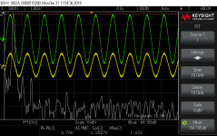
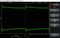
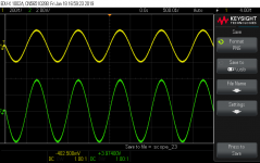
- Image 1 is just to show the amp is working. It shows the input and output with a 1kHz sine wave and an FFT plot.
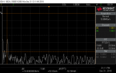
- Image 2 is just the FFT with the signal amplitude set to just before distortion. I’m getting approximately a -52db change between the 0dB and the noise signals after the 1kHz fundamental. I equate this to a voltage ratio of .25% which seems good to me. This is just one frequency but am I looking at it correctly?
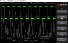
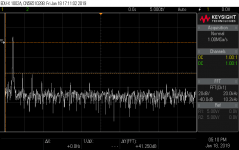
- Image 3 is the FFT with a 1kHz square wave, with NO load. I understand why there are harmonics with the square wave but I don’t understand why there are different harmonics for the positive and negative rails. Also, why are the harmonics on the swing from – to + constant while the harmonics on swing from + to - decrease on the frequency scale.
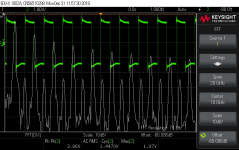
- Image 4 is the same as 3 but with an 8 ohm included. Why does including the 8 ohm load distort the square wave?
- Image 5 is with the Trigger slope set to alternating to zero in on the distortion with the 8 ohm load included.
The amp sounds ok … but I'm just using a cheap speaker. (I fried the cone on it's mate because I made a grounding mistake early on. Lessons learned.)
Thanks for any comments or criticisms. I’ve been lurking on this site for a while but only recently joined.
The images are from my first build, a replica of the Circuit Basics LM3886. A couple of notes on the build:
- This is all assembled on a breadboard using wire wrap. So yes, the wire gauge is only 30 awg. I did this because I wanted to be able to substitute parts to experiment with performance. However, the leads and wire lengths are not always the shortest length possible and that combined with the small gauge might have introduced inductance.
- I’m using a 5 watt 8 ohm resistor for the load. This is just a regular resistor. It’s not a non-inductive etc.
- Power supply is a pair of stacked DC supplies providing 25 volts + or – to each rail.
- The load and the power ground are grounded to the ground on the power supply.
- The signal ground is daisy chained to the power supply ground.
I know this is not an ideal build but it is for experimentation. Would it have an impact on my questions that follow?
- Image 1 is just to show the amp is working. It shows the input and output with a 1kHz sine wave and an FFT plot.
- Image 2 is just the FFT with the signal amplitude set to just before distortion. I’m getting approximately a -52db change between the 0dB and the noise signals after the 1kHz fundamental. I equate this to a voltage ratio of .25% which seems good to me. This is just one frequency but am I looking at it correctly?
- Image 3 is the FFT with a 1kHz square wave, with NO load. I understand why there are harmonics with the square wave but I don’t understand why there are different harmonics for the positive and negative rails. Also, why are the harmonics on the swing from – to + constant while the harmonics on swing from + to - decrease on the frequency scale.
- Image 4 is the same as 3 but with an 8 ohm included. Why does including the 8 ohm load distort the square wave?
- Image 5 is with the Trigger slope set to alternating to zero in on the distortion with the 8 ohm load included.
The amp sounds ok … but I'm just using a cheap speaker. (I fried the cone on it's mate because I made a grounding mistake early on. Lessons learned.)
Thanks for any comments or criticisms. I’ve been lurking on this site for a while but only recently joined.
Attachments
-
 1 - FFT w 1kHz Sine Wave Input & Output 8 ohm Load.png45.5 KB · Views: 247
 -
 2 - FFT 1kHz Sine W max before distortion 8 ohm load.png20 KB · Views: 258
 -
 3 - FFT - 1kHz SQ Wave harmonics no load.png30.4 KB · Views: 239
 -
 4 - FFT - SQ Wave harmonics w 8ohm load.png32 KB · Views: 240
 -
 5 - 1khz SQ Wave w 8ohm load & distortion 8 ohm load.png33.2 KB · Views: 248
Image 4 is the same as 3 but with an 8 ohm included. Why does including
the 8 ohm load distort the square wave?
There is probably an output coupling capacitor, so you get an RC high pass filter
when the load is connected, with a pole at a frequency of 1 / ( 2 x Pi x 8 x C ).
For example, if the output coupling capacitor C is 1000uF (0.001F) , the pole is at 20Hz.
Last edited:
That amp is has obvious instability, clearly shown in the last picture, most likely due to poor layout, and/or incomplete circuit. You really need to build a proper circuit with a good layout to get good results. What you're doing here is a waste of time in my opinion. A member here, "Tomchr" is an expert on utilizing these chips properly, and has some good advise for anyone interested in these amps (here: Taming the LM3886 Chip Amplifier). He also sells some highly praised kits, if you're interested in going that route.
There is probably an output coupling capacitor, so you get an RC high pass filter
when the load is connected, with a pole at a frequency of 1 / ( 2 x Pi x 8 x C ).
For example, if the output coupling capacitor C is 1000uF (0.001F) , the pole is at 20Hz.
Rayma,
Thank you, and yes, there is a high pass filter. I'll study this more.
I wouldn't say waste of time because you've already learnt a good lesson - layout is everything.
Breadboard is nice and easy and keeps everything reusable but it doesn't help when it comes to layout and short lead lengths.
I much prefer to screw the (isolated) chip to a heatsink and P2P solder everything. If I want to change a component, just desolder or snip.
Hands on experimentation is the best way to learn but background reading such as the thread Michael linked to will maximise your time (and enjoyment) and hopefully minimise the amount of smoke released!
Hi Michael and thank you. Maybe a waste of time for you but my goal is to really understand the circuit, not just buy and build a board. BTW, I've studied Tom's article in great detail and replicated most of his simulations. I bought his board too and it really is a thing of beauty but as I said, my goal is to learn. So before I build it, I want to understand what it's doing.
Michael and Avtech23:
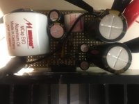
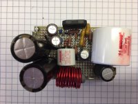
just a quick note. Everything I've read says the layout is everything and Tom C makes that really clear in his writings. I've attached a quick photo. Admittedly, wire wrapping means that lead lengths are a lot longer than they should be but you can see from the photo, I've tried to keep everything tight. As I said earlier in my reply to Avtech23, I'll use p2p as I rebuild this.
just a quick note. Everything I've read says the layout is everything and Tom C makes that really clear in his writings. I've attached a quick photo. Admittedly, wire wrapping means that lead lengths are a lot longer than they should be but you can see from the photo, I've tried to keep everything tight. As I said earlier in my reply to Avtech23, I'll use p2p as I rebuild this.
Attachments
My point about wasting time refers to the fact that there is little to be learned from a bad layout except that they are sub-optimal, and trying to do anything without actually addressing that issue is unlikely to be successful. As Mr. Christiansen says...the layout IS the circuit.
Mike
Mike
That's a good point. Thanks Michael.My point about wasting time refers to the fact that there is little to be learned from a bad layout except that they are sub-optimal, and trying to do anything without actually addressing that issue is unlikely to be successful. As Mr. Christiansen says...the layout IS the circuit.
Mike
there is a high pass filter. I'll study this more.
https://www.electronics-tutorials.ws/filter/filter_3.html
To address the elephant in the room: First of all I'd be throwing out these ginormous Mundorf caps. These may be useful in a rustic tube circuit or a passive loudspeaker crossover, but they have no business being in a circuit like this. Here they spell one thing most of all: Parasitics. Wouldn't be surprised to see some output to input coupling. Use some conventional, "boring" - and most of all: much smaller - options instead (electrolytics, Panasonic / WIMA film caps).
Oh, and - where's the output inductor? Are the components down in the shadows the Zobel network?
Oh, and - where's the output inductor? Are the components down in the shadows the Zobel network?
Last edited:
Thanks srgossklass. I am following the design in the Circuit Basics Lm3886 build but I note that Tom Christiansen does not use them in his build. I'll substitute per your suggestion. Smaller and probably a lot cheaper.
The Zobel network is hidden in the shadows. However, I haven't added the Thiele network. I'm testing using an 8-ohm resistor for the load. Not much by way of lead length so I didn't think it was necessary but I'll go ahead and add it.
The Zobel network is hidden in the shadows. However, I haven't added the Thiele network. I'm testing using an 8-ohm resistor for the load. Not much by way of lead length so I didn't think it was necessary but I'll go ahead and add it.
not quite all, still a very small squiggle
The small oscillations are unrelated to the high pass filter.
They are a conditional instability in the circuit that you need to deal with.
The small oscillations are unrelated to the high pass filter.
They are a conditional instability in the circuit that you need to deal with.
This is turning out to be very educational and I thank everyone for the comments.
Rayma, is the conditional instability likely to be a result of the design of the circuit, a less than optimal layout, poor choice of capacitors, something that hasn't been mentioned yet … or possibly all of the above?
is the conditional instability likely to be a result of the design of the circuit,
a less than optimal layout, poor choice of capacitors
From the scope trace, the stability of the circuit is marginal, and the components
to set the stability may be wrong. Double check the values in the feedback loop
(the two resistors and the capacitor). Also check the output RC network values.
Can you post more photos of the board?
Update
I have completely reworked the amplifier with positive results. (Work and real life intervenes and these things take a while.) Two things stand out:
1. The layout matters. Yes, it was said in this thread and yes, I've read Tom Christiansen's articles and many of his posts in this forum. This post, among others, was also interesting, LM3886 PCB vs Point-to-Point
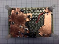
I've tightened up the layout and in a very newbie fashion created wider power traces and ground plains using coper tape. There was no science to the layout of the ground plains (1 each for signal and power grounds) other than they fit the layout. I've attached a pic of the topside and underside of the board using this methodology. I also soldered component leads adjacent to the LM3886 directly to the pins rather than using the perf board.
I'm sure the layout is not ideal but stay tuned for results.
2. Ground. Ground. Ground. Again, thanks to Tom C's Taming the LM3886 Chip Amplifier and others who have written in these forums on grounding. It also helps to read the datasheet. I should have started there. Changes to grounding made all the difference in the world in terms of both audible noise AND the wave form.
3. Finally, I thought this article from Ellliot Sound Products on capacitors was informative.
The attached pictures show the build to this point, top and bottom. (I used an acrylic insulator between layers of copper tape. It looks crude but it was a very effective way to swap out and test components. I've also attached:
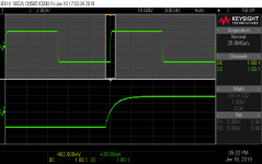
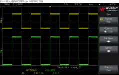
- an oscope shot of the input and output 1 kHz sine and square waves
- an oscope shot of the detail on the output signal square wave showing a small amount of deviation from a true square wave. This is possibly due to the impact of the high pass filter. When I input very low frequencies and 10 kHz and higher, I get the classic shape of the square wave as it changes in relation to frequency input with a high pass filter
- an FFT analysis
The scope images use a 1kHz 500mv input. I'm using a 5 watt 8 ohm resistor for the load.
So how does it sound? In truth, I'm very pleased. I haven't hooked this up to my B&Ws, not sure it would drive a B&W very well, but after thorough testing, I'm using it on an old pair of KEF UniQ towers. No audible distortion, at least of the kind my ears can hear and very nice sound.
I know there are more improvements and I'm sure my layout and execution leave much to be desired but this whole exercise was to learn what makes a chip amp like this tick and I've learned a lot. I also made a lot of mistakes but the two most important lessons were layout and grounding. The difference in what I see on the scope and what I hear from these two elements were immediately discernable, even to a novice.
I'm going to keep experimenting and I want to create a higher power amp, possibly by running the LM3886 in a parallel configuration. I have a pair of Modulus 86 boards that I will eventually build as a final comparison and which I will use in the amp that I want to put into use but this has been a great exercise.
Comments welcomed.
I have completely reworked the amplifier with positive results. (Work and real life intervenes and these things take a while.) Two things stand out:
1. The layout matters. Yes, it was said in this thread and yes, I've read Tom Christiansen's articles and many of his posts in this forum. This post, among others, was also interesting, LM3886 PCB vs Point-to-Point
I've tightened up the layout and in a very newbie fashion created wider power traces and ground plains using coper tape. There was no science to the layout of the ground plains (1 each for signal and power grounds) other than they fit the layout. I've attached a pic of the topside and underside of the board using this methodology. I also soldered component leads adjacent to the LM3886 directly to the pins rather than using the perf board.
I'm sure the layout is not ideal but stay tuned for results.
2. Ground. Ground. Ground. Again, thanks to Tom C's Taming the LM3886 Chip Amplifier and others who have written in these forums on grounding. It also helps to read the datasheet. I should have started there. Changes to grounding made all the difference in the world in terms of both audible noise AND the wave form.
3. Finally, I thought this article from Ellliot Sound Products on capacitors was informative.
The attached pictures show the build to this point, top and bottom. (I used an acrylic insulator between layers of copper tape. It looks crude but it was a very effective way to swap out and test components. I've also attached:
- an oscope shot of the input and output 1 kHz sine and square waves
- an oscope shot of the detail on the output signal square wave showing a small amount of deviation from a true square wave. This is possibly due to the impact of the high pass filter. When I input very low frequencies and 10 kHz and higher, I get the classic shape of the square wave as it changes in relation to frequency input with a high pass filter
- an FFT analysis
The scope images use a 1kHz 500mv input. I'm using a 5 watt 8 ohm resistor for the load.
So how does it sound? In truth, I'm very pleased. I haven't hooked this up to my B&Ws, not sure it would drive a B&W very well, but after thorough testing, I'm using it on an old pair of KEF UniQ towers. No audible distortion, at least of the kind my ears can hear and very nice sound.
I know there are more improvements and I'm sure my layout and execution leave much to be desired but this whole exercise was to learn what makes a chip amp like this tick and I've learned a lot. I also made a lot of mistakes but the two most important lessons were layout and grounding. The difference in what I see on the scope and what I hear from these two elements were immediately discernable, even to a novice.
I'm going to keep experimenting and I want to create a higher power amp, possibly by running the LM3886 in a parallel configuration. I have a pair of Modulus 86 boards that I will eventually build as a final comparison and which I will use in the amp that I want to put into use but this has been a great exercise.
Comments welcomed.
Attachments
- Status
- This old topic is closed. If you want to reopen this topic, contact a moderator using the "Report Post" button.
- Home
- Amplifiers
- Chip Amps
- Newbie looking for help interpreting Oscope images