Going to replace my tone control op-amp(4558) by ne5532. The amplifier i am using has gain of 30db(3886)..& input impedance is 22k. Please help me to achieve proper output from ne5532 for the amplifier. So how much supply voltage for 5532? its a standard circuit from rockola & ok with tl072, ne5532(single). Powered by Symmetrical supply.
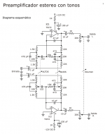
the circuit diagram.
the circuit diagram.
Attachments
If you have well regulated PSU then you do not need those resistors. They are not current limiting but part of the RC filter on each rail to improve PSRR of the circuit. Don't forger to add 0u1 decoupling ceramic capacitors as close as possible to op-amp's power pins.
Regards,
Oleg
Regards,
Oleg
If you have well regulated PSU then you do not need those resistors. They are not current limiting but part of the RC filter on each rail to improve PSRR of the circuit. Don't forger to add 0u1 decoupling ceramic capacitors as close as possible to op-amp's power pins.
Regards,
Oleg
Hi! The power supply is unregulated +/-16vDC MAX.
Ne5532 datasheet says absolute maximum supply voltage of +/-22vDC & i heard that ne5532 doesn't work well below +/-9volt. What should i do? Yeah, thanks for the advice, i will add 0.1uf cap. Maybe this is the cause of that weird noise.
Regards.
A 4558 and TL072 both draw cca 2.5 to 3mA quiescent current. A 5532 draws 8-10mA current (3-4 times as much as 4558 or 072). So yes, a --theoretical-- solution would be to scale the 1K resistors and 100uF caps in the same ratio (f.e. use 330 Ohm resistors and 330uF caps).
Yes, i think so. But what about the gain/output?
any changes? As advised by oleg i will add 0.1uf caps with those.
No, I answerted to your post #1 ; no schematic was visible then.Did you see the diagram Sir? Currently i am using it(5532), but it has a weird noise when turning it off & i think the supply is not enough.
It is necessary for none of them.this circuit has current limiting resistor at supply line.
is it still necessary for 5532?
If you got it from "construya su videorockola" let me warn you that those are quite poor quality designs.
Looks like circuit bits picked here and there and grafted together without too much consideration or ... um .... actual "design" involved.
You know, the kind which involves ... um .... "Math"
 , reading and using datasheet graphs, etc.
 Using those 1k supply resistors is unnecessary ... should I say ludicrous? ... , because they serve no useful purpose and on the contrary chop 3 volts peak or 6Vpp
from output swing. A mess, in exchange of nothing.Given 3 mA consumption fom TL72/RC4558 12V rails now become 9V rails.
Given 8/10 mA consumption by NE5532 rails will now drop to +/- 4 to +/-2V
Besides that: what do you think you will achieve by the substitution?
It´s a Baxandall type tone control, 0dB gain when flat and less than 20dB gain at maximum boost, a light duty where no high performance Op Amp is needed.
Signal level is line level so no audible improvement in noise performance either.
Sadly "Rockola" is a noob magnet because it´s colorful and VERY detailed, including PCB designs and step by step instructions ... it would be way better if they took better care about actual designs.
In a nushell:what you need is a proper clean and regulated +/-15V supply, ... for any and all Op Amps you want to use there.
And that circuit would benefit from a buffer feeding it, so input impedance does not vary with settings and load preamp or signal source feeding it.
Just sayin´
Last edited:
Sadly "Rockola" is a noob magnet because it´s colorful and VERY detailed, including PCB designs and step by step instructions ... it would be way better if they took better care about actual designs.
i know that rockola is totally crap
Probably they stole this design from Cekit. But this circuit works well though not hi-fi type. Do you have any better design? Regards.Agreed. The noise you hear may be from the power supply.
But with 4558 no noise when turning it off.
If I were you I would replace the both 1K resistors with 100 Ohm 1 Watt types, replace the both 100uF caps with the largest value that fit onto the board (something in the 220-470uF range, 16V) and add two 12V 1 or 2W zener diodes across the both caps (something like the ZY12 or the like), which can be soldered on the bottom side of a board. In effect making a passively stabilized +/- 12V supply for the opamps.
The basic design is fine, just feed it well, and if possible add a buffer ahead .But this circuit works well though not hi-fi type. Do you have any better design? Regards.
Or a gain stage, say 5X or 10X gain so system is more sensitive and you can, say, drive it properly from a Phone output
If I were you I would replace the both 1K resistors with 100 Ohm 1 Watt types, replace the both 100uF caps with the largest value that fit onto the board (something in the 220-470uF range, 16V) and add two 12V 1 or 2W zener diodes across the both caps (something like the ZY12 or the like), which can be soldered on the bottom side of a board. In effect making a passively stabilized +/- 12V supply for the opamps.
Alright... i'll add Zeners at power supply board.
thnks for your suggestion.
The basic design is fine, just feed it well, and if possible add a buffer ahead .
Or a gain stage, say 5X or 10X gain so system is more sensitive and you can, say, drive it properly from a Phone output
Actually this circuit works well with phone output...Seriously.
No problem so far...but thank u for the advice
Regards.
If I were you I would replace the both 1K resistors with 100 Ohm 1 Watt types, replace the both 100uF caps with the largest value that fit onto the board (something in the 220-470uF range, 16V) and add two 12V 1 or 2W zener diodes across the both caps (something like the ZY12 or the like), which can be soldered on the bottom side of a board. In effect making a passively stabilized +/- 12V supply for the opamps.
i think it is better to use general voltage regulator(7812/912) than shunt regulator. what do you think? i mean for low noise, ripple etc.
Of course it would be "better" to use 7812/7912 regs .... but can you do it right on the board that you presumably already have?
A 2-watt zener like ZY12 can really save the day in a situation like that.
i know that
i'll put those reg. at main supply board.
Last edited:
Strange old circuit.
It says its a pre amplifier but appears to have no gain.
Its just a buffer and tone control with volume control on output.
It buffers then puts 1k and pot in series with the output.
Sort of defeats the object of the buffer.
then what should i do?
The basic design is fine, just feed it well, and if possible add a buffer ahead .
Or a gain stage, say 5X or 10X gain so system is more sensitive and you can, say, drive it properly from a Phone output
Hi...you was right; the preamplifier was out of gain. i have added a gain stage( first gain stage then preamp). & i am really very sorry for my past misbehaviour.
- Status
- This old topic is closed. If you want to reopen this topic, contact a moderator using the "Report Post" button.
- Home
- Amplifiers
- Chip Amps
- NE5532 for LM3886..need help!!