Hi Guys, I need help. I am building an single supply +36V(SMPS) bridged LM3886 for 100V line speaker. But the problem is that whenever i adjust the VR(PR1) to minimum or maximum, the LM3886 will oscillate and the speaker will make shhhxhhhxhxhhxhxhxhx noise.
I tried to disconnect any input and play with the PR1, it is the same too. After that I did tried to ground the C3, the LM3886 will keep on oscillating, schhshhhchshschhhshshchh noise.
I did suspect the VR problem and i changed a different one, but the problem still there. But it is working completely fine when I turn the VR in the middle.
Any clue what is the possible cause that make the LM3886 oscillate?
Attachments
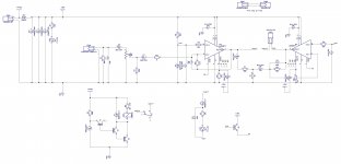
LM3886 has a minimum gain requirement for stability. You look to be violating this when the volume pot is near the centre - at that point the input resistor seen by the device is about 3.5k for a 12.4k feedback resistor. Too low gain -> oscillation assured. The other LM3886 looks potentially unstable too (10k feedback, 2k to AC GND). C5 is wrongly polarized incidentally.
Last edited:
Could be because IC3 is still oscillating in that situation. Its certainly odd that you don't get oscillation at PR1 centre.
Oh I forgot to mention - the absence of zobels (RC on output) isn't going to help stabilty, refer yourself to the typical single supply application circuit (fig2).
Oh I forgot to mention - the absence of zobels (RC on output) isn't going to help stabilty, refer yourself to the typical single supply application circuit (fig2).
Last edited:
Hmm.. I will try not to add the zobels network at output at this moment, I dont know but I think that is not the root cause of this situation.
IC3 sensing a gain of 10k/2k continuously, i will try to increase the gain of IC3 to at least gain of 10 tomorrow. But I am still thinking that is not the root of the problem too...
IC3 sensing a gain of 10k/2k continuously, i will try to increase the gain of IC3 to at least gain of 10 tomorrow. But I am still thinking that is not the root of the problem too...
The circuit does not know or care about what you "think", the minimum you can do is to meet *all* datasheet requirements, doubly so those related to stabilityHmm.. I will try not to add the zobels network at output at this moment, I dont know but I think that is not the root cause of this situation
IC3 sensing a gain of 10k/2k continuously, i will try to increase the gain of IC3 to at least gain of 10 tomorrow. But I am still thinking that is not the root of the problem too...
Only then, you start chasing other problems.
Which I think come from poor grounding/layout first and maybe poor input area shielding.
A heavily inductive load such as a line transformer is also hard to drive and will introduce its own problems.
And you need to add flyback diodes, from each chipamp output to ground and +B to avoid them self destroying when overdriven.
Also post some data about the line transformer you are using.
Are we helping you design a Commercial product?
Hmm.. I will try not to add the zobels network at output at this moment, I dont know but I think that is not the root cause of this situation.
IC3 sensing a gain of 10k/2k continuously, i will try to increase the gain of IC3 to at least gain of 10 tomorrow. But I am still thinking that is not the root of the problem too...
Really ? First off add those zobels. No reason to left these out whatsoever.
Then IC3 isn't seeing a gain of 10K/2K. It's seeing a gain of 10k/1.66k, about 6. Much lower than the required minimum gain of 10 for the lm3886 to be marginally stable. If your layout/decoupling isn't top notch, you really need to up the gain in the 20x range.
Then IC3 is operating as a differentiator, not an inverting amp, because of c15. Not a great idea...
IC1 is in a bad situation gain wise. What did you do exactly to put it to a gain of 15 ?
What's your rationale for the values of the compensation caps ?
Why 20k resistors on the + inputs ?
Why do you bother with c8+c3 or c5+c15 rather than using just one bipolar cap ?
And while we're at it, do your lm3886 come from a reliable source ?
And follow JonSnell advice, your bypass caps for the reference seem low. I don't have time to calculate things but it's all explained in here: Avoiding Op-Amp Instability Problems In Single-Supply Applications | Analog Devices
While I agree with the rest of the post, this is actually not correct in the lm3886's particular case. Flyback voltage protection is integrated into the Spike protection system and no external diodes are needed.And you need to add flyback diodes, from each chipamp output to ground and +B to avoid them self destroying when overdriven.
- Status
- This old topic is closed. If you want to reopen this topic, contact a moderator using the "Report Post" button.
- Home
- Amplifiers
- Chip Amps
- Single Rail LM3886 oscillating