Hi folks
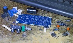
I found this kit n my box of bits, don't recall acquiring it, but the bag it was in had an ebay sticker on it.
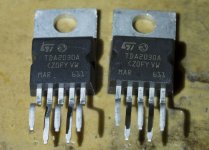
I'm dubious about the components in these kits, the TDA2030s in this one look real enough, but who knows.
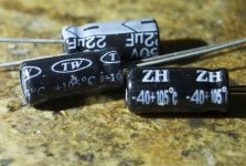
The caps bother me, I probably have the right values in stash to replace them.
The power supply to this thing confuses me, it has no regulator, just a rectifier and a pair of caps.
I found this kit n my box of bits, don't recall acquiring it, but the bag it was in had an ebay sticker on it.
I'm dubious about the components in these kits, the TDA2030s in this one look real enough, but who knows.
The caps bother me, I probably have the right values in stash to replace them.
The power supply to this thing confuses me, it has no regulator, just a rectifier and a pair of caps.
Attachments
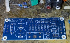
1. Should I trust these kit caps or substitute better quality ones?
2. How does the power supply work without a regulator? What transformer rating should I choose - the power inputs are labelled AC, GND and AC. I have no idea of the wattage rating of this amp or how much current it will draw or what voltage it needs.
2. How does the power supply work without a regulator? What transformer rating should I choose - the power inputs are labelled AC, GND and AC. I have no idea of the wattage rating of this amp or how much current it will draw or what voltage it needs.
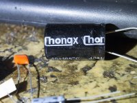
I decided to ditch the kit caps as one of the Chong 3300uF was missing and one of the 22uF was deformed.
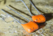
I replaced the 3300uFs with a pair of Nover 2200uF 35V, the 2.2uF with rubycon 3.3uF 50v and the 22uFs with 47uF 25V Nippon Chemicons. The 0.1uF orange caps I replaced with 1.0uF Konek MKT polyester.
I have a 2x12v toroidal that is rated for 30VA, would that suffice?
Thanks for the tip on the TPA3118, I know nothing about chip amps.
...The power supply to this thing confuses me, it has no regulator, just a rectifier and a pair of caps.
Nearly ALL power amps work this way.
AC to rectifier and large cap gives DC. Not ripple-free dead clean, and varies with wall-outlet variations and amplifier demand, but with a little care in the amplifier this is perfectly satisfactory.
Most power amp topologies are fairly resistant to rail ripple. We face Collectors to the rails and the exact voltage is not critical. Heavy NFB reduces what sneaks in.
Adding regulators forces loss of voltage. At the high current of a Power amp, this is major added power required and major added heat. Dollars spent on bigger power transformer, regulators, heatsinks can instead be applied to the power amp's PSRR. Throw in some current-sources, R-C filter input stages, the tricks are endless.
I would not increase 0.1uf caps capacity,if they are connected in series with 1ohm resistor,and connected from output to gnd.These are zobel network part,and its values are critical for amplifier stability, amplifier may oscilate and burn, if you change its values.If cap is connected to pin1, then its input cap,and you may increase it, it will improve low frequency responce.
It looks like you’re on the right track, should sound pretty good I would think.
Could maybe try a snubber circuit on the rectifier, if there’s room, will likely help a bit for not a lot of effort.
The .1uf on the output is tuned to a broad frequency to help snub any emi/rfi that may occur and possibly get back into the amp, causing oscillations.
I have an older el cheapo car amp that has a tda inside, a fun project.
Firstly, apologies for the tardiness of my response, I've been laid up in bed with a nasty leg infection so not looked at the computer for a few days.
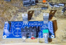
I've finished the amp, just need to find a heatsink to bolt it to, I have some stashed somewhere.
On those 0.1uF caps, they are connected to the output, so I thought they were output coupling caps, but looking more closely, it looks like they are connected between the ground plane and the output, so I better fit a pair of 0.1uF ones, thanks for pointing out my mistake!
From pins 3 and 5 to gnd connected aps are coupling caps ,no problem if you put there 1uf .But from pin4 must be 0,1uf with 1ohm resistor in series ,to gnd .I mean do not short that 1 ohm resistor .I've burned a lots of those tda many years ago ,and it took long time ,until i understanded ,why they burned and that those two parts are critical to not smoke tda's ")
They can be bad clones with worse parameters .I would recomend do not power them directly from rectifier capacitors ,but use a small power rating resistors for + and - rail , lets say 10ohms 0,25W .If they try oscilate at turn on ,resistors will burn and prevent more serious damage .Resistors are much cheaper than ic's .And don't connect speakers for first turn on .If will be no smoke and voltage drop on these resistors small (about 1 volt at 100ma idle consumption),then try to supply signal ,but still no load ,and check how much voltage drops when signal is full power. Fakes may be more prone to oscilate ,so these resistors will show smoke if oscilation occurs .
- Status
- This old topic is closed. If you want to reopen this topic, contact a moderator using the "Report Post" button.
- Home
- Amplifiers
- Chip Amps
- eBay TDA2030 kit build