Hi!
Please guys, I need your opinion before I purchase item in the picture below :
:
The question is the following:
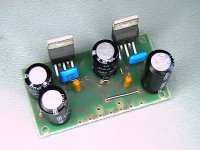
if I replace the two original TDA2003 (on the amp board of the picture below)with two TDA2008, does it work? or could I have problem doing this ICs change?
Please help me!
Thank you in advance
Regards!
Please guys, I need your opinion before I purchase item in the picture below
:The question is the following:
if I replace the two original TDA2003 (on the amp board of the picture below)with two TDA2008, does it work? or could I have problem doing this ICs change?
Please help me!
Thank you in advance
Regards!
Attachments
Hello again!
I hope to not bother you, but I need some advice more!
If you see the picture, you'll notice two 1000uF capcitors (the biggest ones): they're the output coupling capacitors.
My question is: Can I get a low frequency increase if I replace them with two 2200uF capacitors?
And just a last question: I'll feed this amp board with a 18V power supply (so it will be 25 V after the rectifier circuit)...Have I to change other elements on the pcb ( a part of the Volt values of the electrolitc capacitors)?
Thank you so much for your kindness!
Best regards
My question is: Can I get a low frequency increase if I replace them with two 2200uF capacitors?
yes... replace it with higher capacitance will allow for lower frequencies ... you can try to use up to 8200uf capacitor
Hello again!
And just a last question: I'll feed this amp board with a 18V power supply (so it will be 25 V after the rectifier circuit)...Have I to change other elements on the pcb ( a part of the Volt values of the electrolitc capacitors)?
Thank you so much for your kindness!
Just make sure to upgrade those electrolytics caps to 35V or 50V. Thats it and make sure not to exceed the chip maximum voltage
good luck
If you see the picture, you'll notice two 1000uF capcitors (the biggest ones): they're the output coupling capacitors.
My question is: Can I get a low frequency increase if I replace them with two 2200uF capacitors?
And just a last question: I'll feed this amp board with a 18V power supply (so it will be 25 V after the rectifier circuit)...Have I to change other elements on the pcb ( a part of the Volt values of the electrolitc capacitors)?
......yes,2200uF makes sense with a 4 ohm load.
..........a psu with 18Vdc (after rectifier) would be recommended.
why not look into the datasheet?
ST Microelectronics - datasheet pdf
Hi,
as you can read in the datasheet the frequency response of the circuits is 40 Hz to 15 kHz
which isn`t up to date, they were designed for Lo-Fi use in cars or cheap cassette recorders. The output capacitor together with the 4 or 8 Ohm speaker are building a high pass filter to reproduce a frequency of 40Hz you need a capacitor of 950uF with a 4 Ohm speaker or a cap of 500 uF with a 8 Ohm speaker. That means a 1.000uF as in the datasheet will do the job.To have a little headroom and prevent aging issues you can use 2.200uF but 8.200uF doesn't make sense the circuits aren't capable of reproducing this low frequency on the output. I fyou only want to play around with the board using the TDAs is OK, but there are much better integrated amps to buy for little money , i.e. LM3886 or TDA7497 both classic AB amps and not class D.
- Status
- This old topic is closed. If you want to reopen this topic, contact a moderator using the "Report Post" button.
- Home
- Amplifiers
- Chip Amps
- TDA2008 and TDA2003: same PCB ?