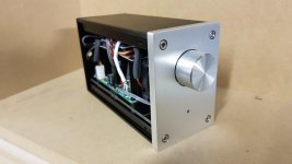
I recently completed a pair of TDA2050 kits to make a desktop amp pretty much one of these:
Tda2050 25W DIY mono brand AB digital amplifier audio sound board kit parts have a fever-in Power Tool Accessories from Tools on Aliexpress.com | Alibaba Group
The amplifier runs single supply 24v (Kit recommends max 25v) and I have paired this with a generic bluetooth module with a 10k Log pot between the BT output and Amp input.
I noticed that the sound quality declines at about 1/3 of the volume range so I put the output on the oscilloscope.
Amp clips at 7.7v into 8 ohms.
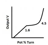
What is strange is that as I turn the potentiometer, up to 1.4v is a smooth increase in amplitude. Then 1.4-1.6v the amp oscillates and the output stagnates. When the output gets to 4.5v, the increase is exponential up to 7.7v where it clips. (See attached diagram).
The behaviour is the same on both channels but the RH oscillates worse - that side has severe oscillation (always around 1.4-1.6Vout) for the first 2 or 3 times I turn the volume knob after a power on. It then stabilises to the previously described behaviour.
Firstly are there any suggestions as to how I can tame this behaviour? I don't think it is normal..
Secondly, is about 7.7v peak out about right for 24v supply on an 8 ohm load? Is 25W into 4 ohm typical Chinese seller optimism? I've confused myself going round in circles trying to do the simple calculation.
Cheers!
Tda2050 25W DIY mono brand AB digital amplifier audio sound board kit parts have a fever-in Power Tool Accessories from Tools on Aliexpress.com | Alibaba Group
The amplifier runs single supply 24v (Kit recommends max 25v) and I have paired this with a generic bluetooth module with a 10k Log pot between the BT output and Amp input.
I noticed that the sound quality declines at about 1/3 of the volume range so I put the output on the oscilloscope.
Amp clips at 7.7v into 8 ohms.
What is strange is that as I turn the potentiometer, up to 1.4v is a smooth increase in amplitude. Then 1.4-1.6v the amp oscillates and the output stagnates. When the output gets to 4.5v, the increase is exponential up to 7.7v where it clips. (See attached diagram).
The behaviour is the same on both channels but the RH oscillates worse - that side has severe oscillation (always around 1.4-1.6Vout) for the first 2 or 3 times I turn the volume knob after a power on. It then stabilises to the previously described behaviour.
Firstly are there any suggestions as to how I can tame this behaviour? I don't think it is normal..
Secondly, is about 7.7v peak out about right for 24v supply on an 8 ohm load? Is 25W into 4 ohm typical Chinese seller optimism? I've confused myself going round in circles trying to do the simple calculation.
Cheers!
Attachments
For the 25W in 4 Ohm the analysis is rather simple: You measure a clipping voltage of 7.7V in 8 Ohm with 24V supply. That is 5.5Vrms. Assuming the clipping voltage would also be 7.7V in 4 Ohm (probably it will be less), the output power is (5.5x5.5)/4=7.5W. So, 25W - no way.
On the oscillation:
It may relate to class AB amplifiers having a varying loop-gain depending on where in the output range the output momentarily is. Said in a different way, the more the amplifier leaves its idle voltage level (in your case probably 12V measured from the negative supply rail), the more loop-gain. This increase in loop-gain can cause the amplifier to oscillate. I have myself noticed a similar phenomenon with an LM1875 (pretty similar to TDA2050). What I noticed on my oscilloscope was one sine-wave half-period suddenly "clipping" by this self-oscillation that would die out again at lower levels. I also had a non-linear output characteristic like you describe.
Good decoupling will always be better but cannot necessarily stop such oscillation.
Try removing the speaker. Do you have the same oscillation problems? If yes, do you see the oscillation on the positive supply pin (pin 5) of the TDA2050? What is the self-oscillation frequency?
Last edited:
Thanks for confirming the figures, Faux. I suspected they were dodgy figures as the datasheet has these at 25W with a +/-25v supply if I remember correctly. So I figured Single supply of 24v would surely be at least half of that quoted figure.
The measurements were taken with an 8 ohm dummy load, no speaker attached. I'll try to make those measurements later but the amp is fully cased up at the mo.
I saw a forum post that said that they had similar experience and needed to add resistance (presumably to the ground of the volume control circuit) but it was very vague. I just wonder if the oscillation has anything to do with the use of the 10k pot affecting the circuit?
Half the supply voltage (total) means roughly one quarter power.
No load is an interesting test because the load current is an important factor in changing loop-gain: My LM1875 behaves well without load or even with 16 Ohm. 8 Ohm starts the problems and 4 Ohm is worse.
In case of self-oscillation, I start with a check for intrinsic instability. Input shorted by 1KOhm and no load - does it oscillate? Then, load on but input still shorted - does it oscillate?
If I pass the two first steps, I go on with the operational instability: Sine-wave input signal but no load - does it oscillate in certain areas of operation? Then, varying loads and sine-wave at the input - does it show temporary instability?
My experience is that such temporary instability is very difficult to fight because it is inherent in the chip.
The 10K potentiometer I do not see as a first worry.
Last edited:
The "fake" ICs is an issued that has been debated a lot on this forum. Most likely "fake" means chips that were discarded in regular legal production due to some non-compliance with specs. The stability issue may be one such reason for rejection. But, if more behave the same it may hint a general problem.
The trouble with buying stuff from China is there are a lot of fake ICs being sold.
Very true. Unfortunately it seems to be the price we pay for paying a small price..
I honestly wasn't expecting very much with this kit being it was so cheap, but I expected a bit more than 8w when it is advertised as 25w.
So I've played around with the amp, injecting 1khz 2v and trying different configurations.
The stability is better when using 4 ohm speakers - I think that is the way to go. It sounds noticeably better on the 4 ohm drivers than the 8 ohm JVCs. I get a little over 8v pk-pk out at clipping so you were pretty spot on there, Faux.
The strange pause in the amplitude increase as I turn the volume up is still there but I guess I'll chalk that one up as a 'design feature'.
This one was a side project and my first proper dabble in chip amps so I won't fuss over it too much, but I'll probably start looking for another chip amp to build. Any recommendations?
Attachments
The majority of Chinese sellers on the Internet are traders without particular technical knowledge. You may look at the range of products they offer to be convinced. They try to make a modest living from re-selling products at very low price.
We are used to much higher prices in return for more precise information. Perhaps your TDA2050 board is not limited to 25V (depends mainly on the voltage rating of the capacitors) and can output more power? The information available at sale is ambiguous. Perhaps not due to bad faith but rather lack of knowledge.
I buy “DIY experiences” from China and I spend no more than I won't regret if it will be a failure in the end. In average, my experiences are very good (for the price) but often I find details I like to improve. I am actually happy that nowhere can they supply a perfect product by highly competent people at the price I buy in China. It would tell me that my competitiveness is even less than I already fear.
Imagine your board was manufactured and sold in Australia and the resulting price. You can find high quality audio modules from Oceania, US/CA or EU but at very different prices. Even from China with a significantly higher price-tag. Where you buy is your choice because you can afford to buy at higher prices, many can't.
This one was a side project and my first proper dabble in chip amps so I won't fuss over it too much, but I'll probably start looking for another chip amp to build. Any recommendations?
It depends fully on what you want to achieve. Super high quality to enjoy for many years ahead, try Tom's "Neurochrome". Western price level but worth every Canadian Dollar you pay. Class AB.
A board or a ready-made amplifier in a box? Perhaps you should try class D this time. A very different design I would have sworn decades ago could sound good. But I have to give in, they sound as good as class AB.
Power level? Do not exaggerate your needs. Many make powerful amplifiers (they actually don't need) just to realize that the power supply needed to supply that kind of power costs as much as the amplifiers.
A board that does not need much "pimping" is based on TDA7498E. Close to 100W for around 25 US$.
I am a concept guy who likes to experiment with different rather cheap amplifier boards and to understand their strengths and weaknesses. My boards are used a couple of months in a lifetime.
I still have a fascination for Tripath amplifier boards though they stopped official production back in 2007 (bankruptcy) but still have an excellent mid-range sound.
"chermann" is specialist in TPA325X boards that are generally of high quality but not without some flaws. Read about his findings in the two threads where he is very active.
The cheap fun most DIYs have been through is a TPA3116 board. From $5 and upwards. You get the 2X30W they state or even more. Not the final amplifier for your lifetime but a lot of fun.
Last edited:
Thanks for all the good info and advice.
My main interest is class AB builds. I tend to get the kits for their PCB and ancillary parts and then replace the sub standard parts with quality parts.
I'm not too interested in class d yet although perhaps the quality of them now has improved from the old class a/ab vs class d arguments.
My main interest is class AB builds. I tend to get the kits for their PCB and ancillary parts and then replace the sub standard parts with quality parts.
I'm not too interested in class d yet although perhaps the quality of them now has improved from the old class a/ab vs class d arguments.
Class AB, then
Aiyima 2PCS MX50 SE 100WX2 Dual Channels Audio Power amplifiers Board Diy Kit New Version-in Amplifier from Consumer Electronics on Aliexpress.com | Alibaba Group
Douk Audio LM1876 Stereo Power Amplifier HiFi Amp Board DIY kit-in Amplifier from Consumer Electronics on Aliexpress.com | Alibaba Group
Amplifier Board DIY Kits LM3886 Power Amplifier 68W+68W Spare Parts Amps Board-in Amplifier from Consumer Electronics on Aliexpress.com | Alibaba Group
All use symmetrical supply voltages. Don't forget the heatsink.
Here is a very compressed video just to illustrate the behaviour of the volume pot.
I was turning the pot steadily but as you can see, the sine wave stagnates (even dips slightly) then shoots up.
This must be the amplifier output. Did you check the potentiometer output?
Here is a very compressed video just to illustrate the behaviour of the volume pot.
I was turning the pot steadily but as you can see, the sine wave stagnates (even dips slightly) then shoots up.
Very informative video. I see no real self-oscillation, only a very non-linear characteristic. It may be the potentiometer. Check the sinewave at the output of the potentiometer - same non-linear behavior? Then, a similar measurement at pin 1 of the TDA2050. Somewhere it misbehaves. When we know where it goes wrong, we may find the fault.
I studied the board parts-list. The large capacitors are rated at 50V. Perhaps it can work with more than 25V supply.
This must be the amplifier output. Did you check the potentiometer output?
I pulled the amp apart again and measured the resistance of the potentiometer.
It looks like this pot is the 'segmented track' type where they cheat and use different resistance pieces along the track to simulate the logarithmic behaviour rather than the more expensive tapered track type. This seems to account for the rather sharp changes in the output.
Next task is to go through the kit schematic versus the datasheet application notes to determine why they have used all 1uF value ceramic caps instead of the values recommended.
Might need to order another set of the kits and do a comparison!
When you go through the design, you may find that you can use a supply voltage higher than the 25V stated in the description and thereby get more output power. At least your TPA2050 chip and power line decoupling capacitors can do higher. There is sometimes very little understanding of the products being sold by such traders. The maximum of 25V may even arrive from the 25V specified in the datasheet but here as a symmetrical voltage (+ and -).
Last edited:
- Status
- This old topic is closed. If you want to reopen this topic, contact a moderator using the "Report Post" button.
- Home
- Amplifiers
- Chip Amps
- TDA2050 Kit Strange Behaviour