Thanks!
Do you think a regulator may improve sound quality. If i use good caps i should get fairly smooth dc, but will the extra smoothness a regulator gives make the amp sound little better.
I use a variable regulated power supply myself but that is because I use it for different amplifiers with different supply voltages.
Having taken many commercial amplifiers apart, also high quality ones, I know that hardly any use regulated (linear) power supplies. I see very competent people making really high performance amplifier designs and using them with unregulated power supplies.
So NO, I do not believe you can hear a difference as long as the unregulated power supply uses good capacitors of a decent size.
The main advantage with a regulated power supply is that you can get a bit more power out of the amplifier because the supply voltage does not sag with loading.
Last edited:
Do you think a regulator may improve sound quality. If i use good caps i should get fairly smooth dc, but will the extra smoothness a regulator gives make the amp sound little better.
A bit of a can of worms this one. Some regulators may improve the sound for some subjects. It is not just ripple reduction.
A bit of a can of worms this one. Some regulators may improve the sound for some subjects. It is not just ripple reduction.
Can you please expand on what you mean. There is a commercial power supply available for this amp and it has several regulators on it.
Are you saying that it is the caps that are resposible for in rush current. I thought it was the toroid, that toroids have large switch on surges and anything over 300va needs a soft start circuit.The bigger the capacitors are, the less ripple you have on the supply rails. But, the bigger they are the more you stress the transformer and rectifier bridge at start-up and with very large capacitors you may need a particular inrush-current limiting circuit.
.
Are you saying that it is the caps that are resposible for in rush current. I thought it was the toroid, that toroids have large switch on surges and anything over 300va needs a soft start circuit.
It is both, but a 300VA transformer cannot scare anyone by itself. It is filling up a large capacitor bank that is often the cause of a current surge with low leakage toroidal transformers.
Would the start up surge from the toroid be ' nullified ' by the capacitors, in that the capacitors would be empty and need filling up at this time, so the surge would be absorbed by the capacitors and not be able to stress any of the components further along.
Yes, the capacitors will be empty and absorb the voltage. What I mean is the surge current filling up the flat capacitors. That surge run in the transformer, rectifier bridge and the capacitors. "Further along" is not involved.
Hi. Thanks for the replies.
One last thing, apart from the multicomp transformer i will need a bridge rectifier and smoothing capacitors for the power supply. Do you have any suggestions as to make or model. Are they all more or less the same. Do Schottky rectifers make a difference. I have skimmed through a few but i do not know what specs to look for in choosing a good rectifier. Is there anything particularly to be taken into consideration.
Also it looks like the right and left amp boards will be being powered by the same power supply. Could i use a capacitor to decouple each board and prevent mutual interference. What do you think of using two electrolytics per board, about 50uf in size, the positive of the first capacitor going to the board positive, the negative of the second capacitor going to the board negative, then the two remaining capacior leads soldered together and sent to the common / ground
Thank you.
Schottky diodes are useful for high frequency switching or rectification of high currents due to the lower forward drop. For 100Hz/120Hz rectification the speed does not matter. The fast and abrupt switching by Schottky diodes may cause ringing with the transformer leakage inductance. Then you need snubber circuits to damp the ringing.
If one rectifier bridge is used, I would use an ordinary KBPC1510 (15A) or KBJ1510, with a small heatsink.
Most stereo amplifiers are supplied from a single power supply using the same capacitors and a single rectifier bridge. You may improve the separation between the channels by using one rectifier bridge (KBU810 / 8A) per channel and two capacitors per channel. I proposed four 6800uF capacitors in posting #20. Then use two capacitors per amplifier and rectifier.
50uF will be insufficient for anything but avoiding self-oscillation. You need 4700uF-10000uF per amplifier and per supply rail.
Last edited:
Thanks for the reply, much appreciated.
For the capacitors, after searching, the nichion kg series have a good reputation someone mentioned the mundorf mlytic as being better.
The nichion can be purchsed for £10 each which is a reasonable price but the mundorfs are £70 each. Have you tried comparing a standard capacitor with a good reuptation against an expensive esoteric and do you think it is worth the extra money. Is there enough of an audible difference to consider purchasing the esoteric.
Thank you.
I have never bought very expensive capacitors for my amplifiers. Even Denon use Nichicon. I use Elna in certain cases. I would never spend more than 10 Pound per capacitor.
You may be able to measure an electrical difference but can you hear a difference? The problem is where do you end up if every component has to be of the highest standards? Are you certain that the Naim modules use only highest standards components? I would balance the costs of the power supply with the costs of the amplifier modules.
There are persons on this forum being much more knowledgeable than me on the topic of capacitors. They may tell you how to get most for your money.
Hi. I got the nichicon kg's delivered today, idon't have any capacitor clips to hold them in place but i do have a hot glue gun.
Is it okay to hot glue them into place upside down so that the leads are pointing upwards, heard that capacitor have a vent that they need to breath through, the vent will be blocked if i hot glue it.
Thanks
Is it okay to hot glue them into place upside down so that the leads are pointing upwards, heard that capacitor have a vent that they need to breath through, the vent will be blocked if i hot glue it.
Thanks
The vent allows hot electrolyte to spew in case of overheating, not pretty. Not all caps have one, only the heavy duty, high ripple current, screw terminal types do. The pcb mountable ones explode in a less controlled manner from the top.
The vent, pointing away from the pcb may reduce damage from corrosion a bit, but this is a a very seldom occurring event.
The vent, pointing away from the pcb may reduce damage from corrosion a bit, but this is a a very seldom occurring event.
There are pro's and con's for and against dc protect.
Its extra circuitry and if it goes wrong it can be a nuisance.
But, it can save precious and expensive speakers.
I have an amp test rig with flying power and speaker leads.
The output goes into a dc protect module and it has saved me a fortune in speakers over the years. I do check for dc on the output before I connect a speaker but I can get the occasional dry joint and moving the pcb breaks a connection and can make the amp output full rail volts into the speaker.
Hi.
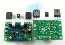
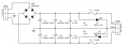
I have got all the parts through to build the amp, but i am trying to figure out where the speaker return (negative) goes to.
I have put up pictures of the power supply and boards.
So far I have +v from power supply going to vcc+ on the boards.
-v from power supply to vee- on the boards.
GND from power supply to GND on boards
Then there is a OUT, partially obscured from view at the top of the board, which i am sending to the speaker positive banana socket
Is that okay so far?
Where does the speaker negative go to?
Also, on the power supply there is a film capacitor, is there any improvement in using a polypropylene at this point rather than a polyester.
Many thanks.
Attachments
Hi.
Where does the speaker negative go to?
Many thanks.
Your opening a can of worms with that question.
Some say to zero volts on pcb while others say zero volts on smoothing capacitors.
I´d go straight to the big capacitors junction, whether they are on board or separate, that is the "zero" point.
If offboard, then I will also connect PCB ground there.
As well as transformer center tap ... that is the "most decoupled" point since it lies straight at the main caps themselves.
IF hum appears when connecting something else, think te Preamp as example, I tend to think I poorly grounded it and try to correct that, but do not lose the main Ground I already have.
As they always say, YMMV")
If offboard, then I will also connect PCB ground there.
As well as transformer center tap ... that is the "most decoupled" point since it lies straight at the main caps themselves.
IF hum appears when connecting something else, think te Preamp as example, I tend to think I poorly grounded it and try to correct that, but do not lose the main Ground I already have.
As they always say, YMMV
- Status
- This old topic is closed. If you want to reopen this topic, contact a moderator using the "Report Post" button.
- Home
- Amplifiers
- Chip Amps
- why no dc protection