This is intended for my DSP based multi-I/O headphone adapter module. I need a fixed gain OPA+BUF, but the chip selection is problematic.
Specifications (that I am certain) are:
* Upstream: analog output from ADAU1761. Can be differential, can be single ended. Contains a DC bias referenced from a pin on ADAU1761.
* Downstream: Apple EarPods
* Supply voltage: +3.3V only. Have to be RRIO for the sake of output range.
* No need to add volume controls. ADAU1761 has internal PGA for both input and output volume controls.
Questions:
* Is LME49721 OPA + LMH6623 BUF good enough?
* How to implement fixed OPA + BUF with a differential input signal?
* How to shift the DC bias level?
Why wouldn't you use a single IC solution for headphone outputs? Just use OPA1688 or OPA1622 which are designed for such duty. The only drawback is that both require >4V supply.
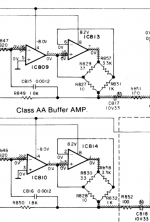
For the differential input configuration look at the typical application diagram in the OPA1688 or OPA1622 datasheets. The op-amp + buffer config can be seen in the LME49600 datasheet. With the single rail supply you should not shift DC bias level since you need it for correct circuit operation and you should use an output coupling capacitor. Things become significantly easier if you can use bipolar supply for the analog output stage.
For the differential input configuration look at the typical application diagram in the OPA1688 or OPA1622 datasheets. The op-amp + buffer config can be seen in the LME49600 datasheet. With the single rail supply you should not shift DC bias level since you need it for correct circuit operation and you should use an output coupling capacitor. Things become significantly easier if you can use bipolar supply for the analog output stage.
According to this very excellent table of headphone data, an output current of 60mA RMS is sufficient to drive all but the most ridiculously low sensitivity (Hifiman) headphones. So you need to see a datasheet Ioutmax spec of ~100mA, accounting for RMS-to-DC and margin-to-spec.
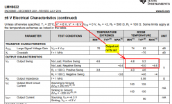
Operating from (3.3V, 0V) supplies, you won't be able to accept the two Vbe drops of a standard BJT Diamond Buffer circuit like BUF602 or BUF634 or LH0002. Instead you'll need to use a pair of high current, rail-to-rail opamps in push-pull ("bridge") configuration. This one might be a pretty good fit. 3.3V supply, RRIO, 220mA output current.
Operating from (3.3V, 0V) supplies, you won't be able to accept the two Vbe drops of a standard BJT Diamond Buffer circuit like BUF602 or BUF634 or LH0002. Instead you'll need to use a pair of high current, rail-to-rail opamps in push-pull ("bridge") configuration. This one might be a pretty good fit. 3.3V supply, RRIO, 220mA output current.
I cannot actually use that push-pull configuration doe tot he pinout of Apple EarPods. There is a common ground pin for both earbuds and the mic/remote.According to this very excellent table of headphone data, an output current of 60mA RMS is sufficient to drive all but the most ridiculously low sensitivity (Hifiman) headphones. So you need to see a datasheet Ioutmax spec of ~100mA, accounting for RMS-to-DC and margin-to-spec.
Operating from (3.3V, 0V) supplies, you won't be able to accept the two Vbe drops of a standard BJT Diamond Buffer circuit like BUF602 or BUF634 or LH0002. Instead you'll need to use a pair of high current, rail-to-rail opamps in push-pull ("bridge") configuration. This one might be a pretty good fit. 3.3V supply, RRIO, 220mA output current.
Then you are going to have a very difficult time driving the output to 4V RMS (±5.6V peak to peak) as required by the Beyerdynamic T1 (and other) headphones, even after disqualifying the Hifiman weirdos.I cannot actually use that push-pull configuration doe tot he pinout of Apple EarPods. There is a common ground pin for both earbuds and the mic/remote.
If your output pin swings between Vmin (hoped to be 0V but higher in reality) and Vmax (hoped to be 3.3V but lower in reality) then its RMS output voltage is easy to calculate:
- V_out_rms = 0.5 * (Vmax - Vmin) / sqrt(2)
I actually don't intend to drive those hard ones at all - from the first post the intended target device has been Apple EarPods and compatibles. The design in question even have remote control decode logic for crying out loud, and I doubt if Beyerdynamic T1 would have one compatible with Apple's protocols...Then you are going to have a very difficult time driving the output to 4V RMS (±5.6V peak to peak) as required by the Beyerdynamic T1 (and other) headphones, even after disqualifying the Hifiman weirdos.
If your output pin swings between Vmin (hoped to be 0V but higher in reality) and Vmax (hoped to be 3.3V but lower in reality) then its RMS output voltage is easy to calculate:
When you crank the numbers I predict you'll find, that Vout_rms will work with about half of the headphones in the table
- V_out_rms = 0.5 * (Vmax - Vmin) / sqrt(2)
- Status
- This old topic is closed. If you want to reopen this topic, contact a moderator using the "Report Post" button.
- Home
- Amplifiers
- Chip Amps
- Chip selection for a fixed-gain low-voltage OPA+BUF