You're not going to have fun etching at home. But here are the top and bottom in pdf.
Some points of attention:
- I didn't include all the vias in the print. You will have to see where you want some (and you absolutely need some right at the top near the lone smd resistor). The pictures from post 58 will guide you for that.
- Depending on your process, you might have to mirror the bottom (it's as seen from the top in the pdf).
- The board dimensions are 60*50mm. So you can check if you print it out at the right size.
- If I were to do it, I would probably edit the pictures to remove the top ground planes (right at the middle and at the right of the board).
- As usual, the worst parts to deal with will be the electrolytic caps.
- Eagle puts pads even at the side to which the components aren't connected (they're tht pads). You might want to etch or scrap these out to get more clearance in a pcb without mask.
Can you mark the points which connect top layer to the bottom layer
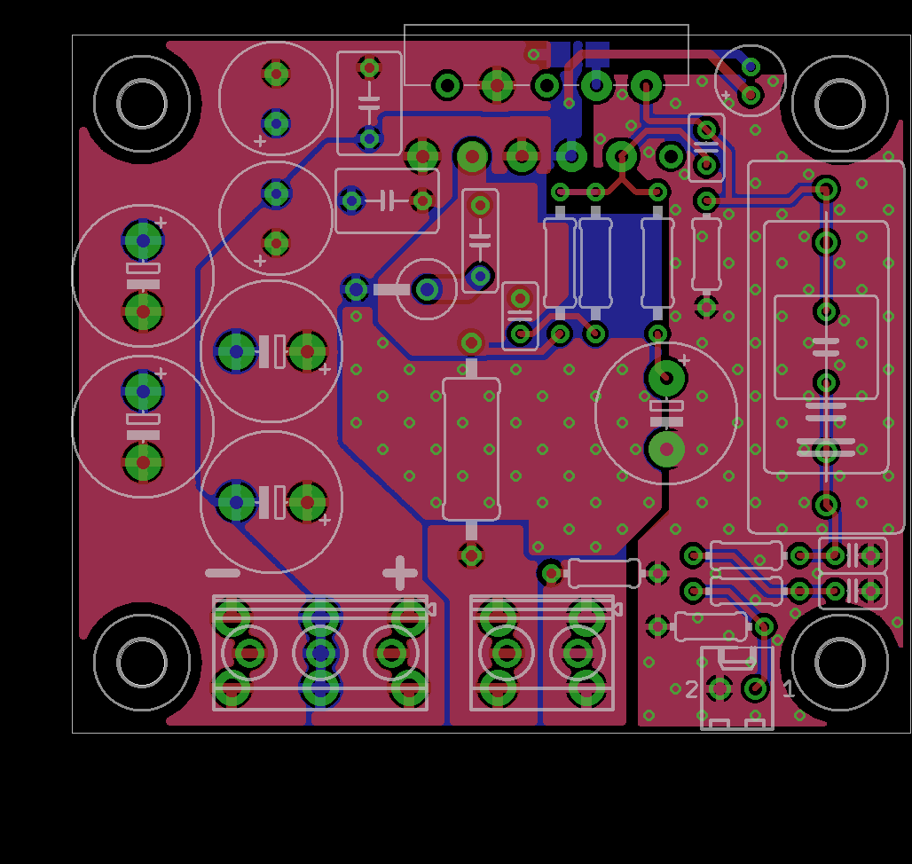
Check the pic below. Anytime there is a small green circle, there's a via connecting top and bottom. Right in the middle of the lm3886, at the top of the board, you have two vias actually doing connections. All the others are there for stitching, connecting two groundplanes. You don't need that many probably.
For the rest, connections should be obvious from the layers.
For the rest, connections should be obvious from the layers.
Check the pic below. Anytime there is a small green circle, there's a via connecting top and bottom. Right in the middle of the lm3886, at the top of the board, you have two vias actually doing connections. All the others are there for stitching, connecting two groundplanes. You don't need that many probably.
For the rest, connections should be obvious from the layers.
Thanks a lot, that is very helpful.


Check the pic below. Anytime there is a small green circle, there's a via connecting top and bottom. Right in the middle of the lm3886, at the top of the board, you have two vias actually doing connections. All the others are there for stitching, connecting two groundplanes. You don't need that many probably.
For the rest, connections should be obvious from the layers.
I have searched through pages but cant seem to find bom. Can you kindly post it.
Regards
See post 40. However that BOM has one error as it is missing one single smd resistor (1206 size, 22K) and doesn't include the connectors. See also post 129 for a simplified BOM.
A completed BOM has been posted by NealJ here : https://enjon.uk/wp-content/uploads/2019/08/Mouser-lm3886-updated-project-bom.pdf
A completed BOM has been posted by NealJ here : https://enjon.uk/wp-content/uploads/2019/08/Mouser-lm3886-updated-project-bom.pdf
In my case, the toner transfer method worked best using Acetone. The PCB is printed and fixed to a blank PCB laminate facing the copper with tape. Make sure the print does not move and is held secure. Then, apply the acetone to the exposed part of the printed paper. The acetone will wet the paper and the toner will dissolve. With the PCB held horizontal and the print facing upwards, gently massage the paper to add some pressure to help the toner fix itself to the copper laminate. When the acetone dries, the whole thing is placed in water to for the paper to soften. The soft paper is then removed with the tip of a finger. The last part is the most critical and requires the use of a paper which easily breaks down when wet. The paper has to satisfy the requirement of being tough to remain the same size when acetone is applied and to be easily removed afterwards with the tip of a finger or something delicate enough not to damage the print.
There is yet another method which uses a mixture of alcohol and acetone to avoid the need of having to scrape off wet paper. The alcohol permits the acetone to easily detach itself from the paper. The method is quite quick and accurate but requires a custom press.
There are at least two youtube videos describing the above. Be careful as many videos make many claims without results.
updated BOM (again)
Someone pointed out to me that the revised BOM had C6 missing. Not sure what happened there, so apologies for that, but I've updated it now, please use this link
https://enjon.uk/wp-content/uploads/2020/09/Mouser-lm3886-updated-project-bom.pdf
See post 40. However that BOM has one error as it is missing one single smd resistor (1206 size, 22K) and doesn't include the connectors. See also post 129 for a simplified BOM.
A completed BOM has been posted by NealJ here : Page not found – (mis) Adventures in Hi-Fi
Someone pointed out to me that the revised BOM had C6 missing. Not sure what happened there, so apologies for that, but I've updated it now, please use this link
https://enjon.uk/wp-content/uploads/2020/09/Mouser-lm3886-updated-project-bom.pdf
I wanted to share my build.
Using the open source Lm3886 boards, I have a great sounding amp.
Boards were stuffed as per 009400 posts, the earth stars work perfectly (separate for signal and power).
Note:
the transformer is a 300va 18v Toroidy audio model
the single power supply is from BrianGT chipamp (10,000uf per rail plus snubbers ala carlosfm)
dual speaker outlets make it easy to bi-wire the speakers
mains supply live, earth, neutral all suppressed with Y2 capacitors
No discernible speaker hum, or mechanical hum. No pops or clicks when from any home appliances.
I know the mind plays tricks, but I am sure that the sound has improved each day since switch on. It seems to me that component burn in is real, that our creations do need time to settle in.
IMG_0538.jpg - Google Drive
IMG_0539.jpg - Google Drive
See post 40. However that BOM has one error as it is missing one single smd resistor (1206 size, 22K) and doesn't include the connectors. See also post 129 for a simplified BOM.
A completed BOM has been posted by NealJ here : Page not found – (mis) Adventures in Hi-Fi
Hi,
ordered PCB and waiting for parts. Thank you very much for your efforts!!
One question: I have a nice encapsulated transformer: 25-0-25 V (225 W), can I use it or tension is too elevated for this application? I've seen that the usual voltage is 18-22 V
Tks
I have a nice encapsulated transformer: 25-0-25 V (225 W), can I use it or tension is too elevated for this application? I've seen that the usual voltage is 18-22 V
Tks
A 25v 0 25v AC transformer will rectify to about 35 -0 - 35 DC (x 1.414)
The LM3886 datasheet states that this voltage would be OK
However, when using a speaker with an impedance of 4 to 8 ohms, a lower voltage is better, as the output power can be better maintained for lower impedance speakers. (assuming your speakers are somewhere in the range 4 to 8 Ohm)
My advice, aim for 18-0-18 V AC, with power of 225 to 300 VA for a 2 channel amp.
The link below takes you to a great page on this topic
Taming the LM3886 Chip Amplifier: Output Power – Neurochrome
Last edited:
Your transformer will work and since you have it already, I would certainly try it. As mentioned a 4-ohm load at higher volumes might cause the SPiKE circuit to kick in, which will give you a scare the first time you hear it.
I listen at pretty normal levels (75-80db at 6 feet) and have not any issues even with 4-ohm speakers using +/-36Vdc. YMMV of course.
I listen at pretty normal levels (75-80db at 6 feet) and have not any issues even with 4-ohm speakers using +/-36Vdc. YMMV of course.
I've got to agree with what said. 25vac is higher than optimal but fine in less demanding loads.
Ideally, I'd suggest a 2*21vac, 120 to 160va transformer for a stereo build in a domestic setting. There is a good post on transformer va rating here: https://www.diyaudio.com/forums/sol...spect-wattage-power-amplifier.html#post432191
Ideally, I'd suggest a 2*21vac, 120 to 160va transformer for a stereo build in a domestic setting. There is a good post on transformer va rating here: https://www.diyaudio.com/forums/sol...spect-wattage-power-amplifier.html#post432191
There must be a hundred threads about the lm3886 basic implementation. Some good, some awful. Wouldn't it be nice to have a fool proof pcb-schematic-BOM set we can refer beginners to ? Maybe not the ultimate fidelity or the most tricked up design ever but just a solid, decent performer ? The pcb would provided as tested gerber files.
Here's a first suggestion up for criticisms/improvements. It's based on a smaller smd design which works quite well in practice but for a simple board I moved everything back to through hole (except for the muting resistor).
Nothing extravagant. A few options are provided for the input cap and the output/PS connectors can either be screw terminals or faston. The board is 65*50mm. All electrolytic caps are sized for 50Vdc caps. The resistors at the input are 125mW, the ones in the feedback network 500mW.
Final version:
I leave this first post pretty much untouched but the layout attached isn't perfect yet of course. The final version can be found here: An open source layout for the lm3886 ? - Page 6 - diyAudio
Eagle and gerbers files:
The PSU is at post #63 of the thread, the protection board at post #121 and the amp board at post #80.
Acknowledgement:
- This layout for the lm3886 has been made possible by the wealth of information given by Tom Christiansen, on his website neurochrome.com and on this forum (see especially this seminal thread, among many others).
- In this thread, I'm particularly indebted to the contributions of Mark Whitney and bozoc who pushed things in the right direction and corrected me when needed.
Any chance up uploading the final versions of all three boards (PSU, DC Protect & Amp) to Osh Park for easy ordering of all three?
I've got to agree with what said. 25vac is higher than optimal but fine in less demanding loads.
Ideally, I'd suggest a 2*21vac, 120 to 160va transformer for a stereo build in a domestic setting. There is a good post on transformer va rating here: https://www.diyaudio.com/forums/sol...spect-wattage-power-amplifier.html#post432191
Thank you, good to know. My speakers are quite an easy load
M
- Home
- Amplifiers
- Chip Amps
- An open source layout for LM3886?