Something I've been toying with. Marginal improvements.
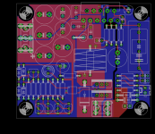
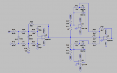
- Now the DC protection is onboard.
- All resistors are 10mm spacing (so no need to order small 1/8w resistors).
- Reverse parallel diodes can be fitted in // with the hum breaking resistor.
- That network can be jumpered.
- The board grew a bit to 60*70mm (from 50*65mm).
- Now the DC protection is onboard.
- All resistors are 10mm spacing (so no need to order small 1/8w resistors).
- Reverse parallel diodes can be fitted in // with the hum breaking resistor.
- That network can be jumpered.
- The board grew a bit to 60*70mm (from 50*65mm).
Attachments
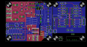
I should probably start a new thread but... what I'm working on currently is adding an opamp stage before the lm3886 on the same pcb, that could be used as either HPF or LPF LR4 filter to create a simple analog crossover and baffle step compensation. Something like 1/4 of the esp09. I think I can fit that in a 7*10cm pcb.
That's gonna be hard without using smd... 7*12cm seems more reasonable. Here is a first draft.I think I can fit that in a 7*10cm pcb.
4 opamps sections, with quite a bit of flexibility. The board could be used for bridging, sub summing and filtering, an analog crossover, etc. My aim was to develop something I could easily stick into an active monitor.
- First one can be configured either as a simple buffer/gain stage, as a non inverting summing amp or as a balanced line receiver.
- The sections 2 and 3 (top opamp) can be configured as either hpf or lpf Sallen-Key filters, with 2.54 or 5.08mm spacing caps.
- The last section is a simple gain/buffer. It can be either inverting or non inverting.
Between 3 and 4, there is a level control and after 4 a BSC control.
For power, the idea is to tap the power lines, with a 24V to +/-12V dc-dc converter. 1W ones are quite cheap and sufficient here.
Attachments
Yes, baffle step compensation. A buffer would be needed if the following amp has a low impedance input (lower than about 20k as suggested by ESP). Not a problem here.
I must confess I let this a bit aside for now as my need for it has been delayed. In the meantime, more as a kind of challenge than a serious endeavor, I'm toying with a layout for a zd-50.
I must confess I let this a bit aside for now as my need for it has been delayed. In the meantime, more as a kind of challenge than a serious endeavor, I'm toying with a layout for a zd-50.
Attachments
You mean the active crossover ? I don't think it would be too good standalone; better to provide a full two way analog crossover then, such as the tidu035 from TI. A modified all through hole version of that thing might be nice. But yeah, it certainly would be better in a new thread.
I wanted to do the same thing but cannot find the time.I'm toying with a layout for a zd-50.
I noticed that ZD-50 power rails are regulated, wonder how the amp would perform(it would probably not take a bit hit on performance) on unregulated supply...
The designer wrote somewhere that it wouldn't be a big hit indeed but that he wanted to extract as much performance as he could out of his amp. That's why he also included the output relay inside the feedback loop and didn't include a clipping circuit. He also used a 4 layers board and designed the amp as a monoblock from the start.
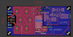
This board is more modest, with 2 layers only, unregulated supplies, the protection mosfets outside the feedback and a clipping circuit at the input. Rather than the klever klipper from Cordell, I used the feedforward clipping circuit from D. Self. Alternative layouts can already be found on the Russian forum where the ZD50 was initially posted but they didn't exactly have what I wanted.
This board is more modest, with 2 layers only, unregulated supplies, the protection mosfets outside the feedback and a clipping circuit at the input. Rather than the klever klipper from Cordell, I used the feedforward clipping circuit from D. Self. Alternative layouts can already be found on the Russian forum where the ZD50 was initially posted but they didn't exactly have what I wanted.
Hi 00940, did you test your mono dc-protect, you did not give any feedback thanks, amazing workI've sent the lm3886 files to smart proto. I should have the pcb on hand in one month or so...
Meanwhile, I redid the dc-protect board. I didn't like the format. This pcb is made to be directly mounted on standard 19mm pitch speaker posts. It's also mono. Having one detector for stereo only saves a few resistors and cheap transistors, not really a big deal.
I'm toying with a layout for a zd-50.
This one seems to be also interesting : Composite versterker "De brainstorm" - forum.zelfbouwaudio.nl
Hi 00940, did you test your mono dc-protectk
Yeah, I need to properly test the voltages at which it's kicking in. It works (with crude testing). Another issue was that the faston connector is too close to the hole for the speaker connector. It's ok for the nuts but a wide-ish wafer might be a problem.
This one seems to be also interesting : Composite versterker "De brainstorm" - forum.zelfbouwaudio.nl
Indeed. I'm going to give it a look in ltspice, to see what stability looks like. Certainly much simpler than the zd50... maybe a good thing, mabye not.
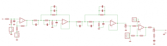
In the zd50 I'm working on, I've included an external clipping circuitry. It is taken from D. Self and goes like attached. It has the great advantage of kicking in very precisely and being out of the way the rest of the time.
Attachments
Yeah I like simple things.Indeed. I'm going to give it a look in ltspice, to see what stability looks like. Certainly much simpler than the zd50... maybe a good thing, mabye not.
I'd like to replace my simple lm3886 amps by composite one's.
There was a group buy from this project, no instabilities reported.
Unfortunately the opamp that was used is not available anymore and the schematic corresponding to the group by is not published. I spend some time trying to reverse engineer the feedback topology from fotos of the pcb and it seems almost to correspond to the schéma posted in thé first thread .
If you have a valid lm3886 lt Spice model to share, i would bé glad to play also a bit 😉
I'm using the model provided by the designer of the zd50 here: ????????? ???????? ZD-50
Hi 00940, I ordered pcb,s of your amp boards ps and dc protect. I was also expecting follow up info on the above dc protect. It seems the original goal has been lost in the process, as I thought a simple beginner board was the point of the post. Unfortunately you have lost me now.
- Home
- Amplifiers
- Chip Amps
- An open source layout for LM3886?