Hello,
I would be very flattered if I could present my new project here, sharing this my experience among serious audio experts like you are, and maybe have here a Q&A section.
What I reported herebelow is the exact replica of my new web site where you can also enjoy some extra pic.
Website: [url=https://ggianluca.wixsite.com/opamplifier]50thanniversary[/URL]
IMPORTANT DISCLAIMER: today, 2018, manufacturer Linear Technology (LTC) is full part of Analog Device (ADI), but at the time of this design they were two distinct semiconductor companies, thus, I'm going here to mention them separately. This is an independent hobbyst project: either LTC or ADI do not have any association with this work. The information here presented is believed to be technically correct.
Conception
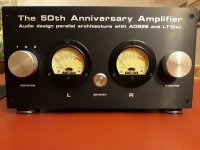
I named the amplifier "The 50th Anniversary" because I built it as a gift to myself for my 50th birthday.
This project comes from the heart and its conception was simple: as I am a big enthusiast in my hobby audio applications of the tonal flavour of AD826 (ADI) and LT13xx (LTC) opamp family, why not build an amplifier powerful enough to drive loudspeakers by connecting many of these chips in parallel?
How would the sonic signature be mixing them together?
It is worth mentioning that none of these video opamps was designed for audio application by their manufacturers.
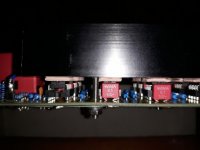
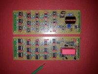
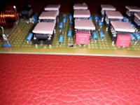
Sixty chips, $5 heterogeneous ADI and LTC dual video operational amplifiers in DIP8 package, were paralleled and work in unison in the audio band by sharing
the same feedback in a master-slave configuration.
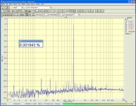
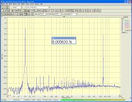
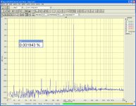
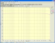
There are sixty opamps per audio channel, so 120 opamp in total, each capable of supplying 50mA individually, which provide more than 3 Ampere current when paralleled. This is adequate to drive a pair of common 8-ohm loudspeakers at 10W power with minimal distortion and excellent linearity (0.002% THD @1Wrms; 0.006% IMD; +-0.1dB over 20-20kHz; >100dB SNR, what measured by me with non-professional PC sound card).
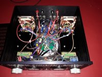
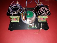
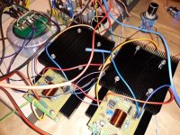
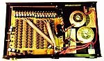
The amplifier is built on modular stacked high-quality fibreglass prototyping boards with multiple hole connections and power rail printed patterns and the
circuit was designed with the aid of LTSpice, a freeware software circuit simulator created by LTC.
Master-slave configuration
The idea is far from to be innovative as Douglas Self in 2010 already published a superb modular power amplifier in Elektor using a massive number of cheap NE5532 opamps in a grid configuration.
Before this, many semiconductor manufacturers proved in their datasheets (OPA111, LT6020, AD826 etc..) that it is safe to put in parallel 'N' stage of opamps to reduce the relative amplifier noise and increase the output driving capability.
But "The 50 Anniversary" differentiate itself by adopting a master-slave configuration. In this design a single opamp (the "master") feeds several other
opamps (the "slaves") all placed within the master feedback loop and wired in parallel as unity gain current buffers replicating the master output voltage.
With the master feedback being wrapped around the entire net of slaves, overall accuracy is maintained.
This approach is only effective at low frequencies such as audio, where the propagation delay of the slaves is negligible with respect to the wavelength of the input signal, so that the phase shift will not cause wasted current and distortion. You may find interesting readings about this topology in few
application notes (like Intersil AN1111 or Apex AN-26) and in various datasheets (like OPA511).
Because during the model simulation LTspice displayed excessive "ringing" at the output of square-wave pulses into capacitive loads, stability was improved by adding external compensation (a shunt capacitor across the master feedback resistor) small enough to don't jeopardise the bandwidth of these fast opamps.
Different opamp sound different
"The 50 Anniversary" also combines mixed types of opamps. If you listen carefully, you may perceive some tonal changes and psychoacoustic variations when connect identical or different opamps (either in series or in parallel).
My preferred opamp is the AD826 (ADI), which is smooth, open, clean and sounds true to life in mids and voices: this opamp reproduces the best female voice I've ever heard among any op amp tested.
To me also the LTC family of fast bipolar opamps LT1355, LT1358, LT1361 and LT1364 is audio superb!
The LT1358 (LTC) is warm, bright, tonal rich and sounds forward.
The LT1364 (LTC) is dynamic, fullness, punching bass and sounds accurate.
Consequently, for the "master" amplifier it was chosen the AD826 (ADI) which alone pilots, at a gain of two, an equal mix of 59 (per channel) parallel AD826 (ADI) and LT1364 (LTC) in unity gain configuration. The pleasing parallel combination of the AD826 (ADI) with LT1364 (LTC) compensates for each other's sonic difference and exhibits the lowest listening fatiguing.
Both AD826 (50Mhz; 350 V/us) and LT1364 (70Mhz; 1000V/us) opamps exhibit outstanding technical specifications, quite difficult to find all in one sole amplifier: bipolar, single stage, handling all capacitive loads, suited to drive cables, unity gain stable, hi-current output (50ma min), wide bandwidth (>50Mhz), extremely high slew rate, low-impedance driving capability (150 ohm), class AB output stage, easy to assemble in DIP package.
Also LT1208 (LTC) has stunning sonic and technical performances, comparable to AD826 (ADI), but it has half of its current capability, hence, it was discarded.
The pre-amplifier section is made by one half of AD826 (ADI) as buffer input in series with one half of LT1358 (LTC) that provides most of the gain after the volume control: both are biased in class A by using Warren Young (tangentsoft.net/audio/) constant current source JFET cascade configuration. They have their own dedicated power supply using best-in-class complementary LT1963A/LT3015 (LTC) low noise low dropout regulators.
Chip heat dissipation
The main concern I had for this project was realizing a good cooling system because DIP packages are not intended to be mounted on heat sink at all.
Epoxy plastic is also not conductive: a DIP8 package has poor junction-to-ambient resistance, 130Cdeg/W for LT1364 (little better in AD826), hence, without cooling system, it can dissipate only one watt at 20degC ambient temperature, reaching the maximum permissible internal temperature of 150degC.
All electrical circuits dissipate some power in the form of heat. Usually both LT1364 and AD826 run very warm even in standard application because their quiescent current is elevated (7.5mA per amplifier) being hi-speed bipolar devices: higher currents mean higher slew rates on internal nodes.
Heat wears out electronic components; as described by the Arrhenius effect equation, every 10degC increase in working temperature reduces component life by half.
The power dissipation on a single chip in this design could potentially reach nearly one watt (~500mW per opamp) in worst conditions, which I select to occur driving a reactive 6 ohm load with 60deg phase angle, like could be a tough home loudspeaker.
Worst case thermal analysis
Calculations for heat dissipation in reactive loads are complex due to the phase difference between voltage and current, but Apex AN08 "Optimizing Output Power" application note helps with some 'turnkey formulas' which I have expanded here. I considered a pure sine wave signal for simplicity, which is rather cautious, since the long-term average levels for the audio tracks are much lower, depending on the type of music.
Power dissipated = PD = PI + PO where:
PI = power drawn from the power supply =
= DC power supply * AVERAGE output current + PQ =
= Vcc * 0.9 * Iout_RMS + PQ= 0.637 * Vcc * Vout_peak / |ZL|+ PQ
PQ = quiescent power supply =
= I_Quiescent * 2 * Vcc
PO = real power delivered to the load =
= Iout_RMS * Vout_RMS * cos(fi) = 0.5 * Vout_peak^2 / |ZL| * cos(fi)
|ZL| = 365 ohm, that is 6 ohm load shared among 60 opamp, plus Ro
|Ro| = 5 ohm, output resistor mandatory to prevent the parallel opamps from fighting each other
cos(fi) = cos (60deg) = 0.5
Vcc = +-15V
Vout_peak = max output swing before clipping = 13.7V
I_Quiescent = max supply current = 7.5mA
PI = 0.637 * 15 * 13.7/ 365 + PQ = 359mW + PQ
PQ = 7.4 * 2 * 15 = 222mW
PO = 0.5 * 13.7^2/ 365 * 0.5 = 129mW
PD = PI + PO = 452mW per opamp
Power dissipation per chip = 2 * PD = 904mW ~ 0.9W
Unbalanced output currents were not taken into consideration here.
Heat dissipation of 0.9W would rise the junction temperature to 117degC (=130*0.9) above ambient: because air temperature inside a cabinet might reach 47degC in summer, the chips will likely get damaged as their dies go above 150degC.
In fact, the indoor temperatures of houses in temperate zone could reach 35degC in July-August and the temperature rise inside a vented cabinet of a power amplifier rated like this, is approximately 12degC above external.
Hence, some effective cooling methods had to be adopted in this project.
Cooling methods
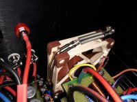
First the cabinet has a fully vented top cover in substitution of the standard one and is equipped with high feet: this improves natural air convection moving hot air out from the top. The temperature rise, delta T, inside the cabinet was reduced from 12deg to about 10degC above external, internally reaching 45degC in hot summer.
Second, four heat sinks were screwed onto the perfboards, each covering fifteen DIP8 chips (or 30 opamps): the purpose of the sink is to remove heat from the top surface of the chips and distribute it to the ambient. Heat sinks were selected rather large offering a natural convection thermal resistance of 1.7degC/W. But mounting them horizontally instead of vertically, like here, the natural airflow will be less effective, and the thermal resistance must be increased by about 15%, hence, to about 2degC/W.
Because fifteen devices dissipate 13.5W in total, we can expect the temperature of the heat sink (and consequently of top surfaces of the chips) to rise 27degC (=2*0.9*15) above ambient.
Given the temperature difference (per watt dissipated) between the die and the surface of a P-DIP8 device (called "Theta JC", 50degC/W for LT1364, which is in general about 2/5 of that to ambient), these chips would reach a maximum internal temperature of 117degC (=50*0.9+2*0.9*15+45) in hot summer and in worst power condition, at 0.9W.
Cooling multiple chips with a single heat sink is attractive but can create serious thermal issues: due to the differences in assembly of fifteen chips mounted in sockets, heat sink would not cover completely all chips because their top surfaces will be hardly coplanar. To prevent this, a thick (1.5 mm) and flexible thermal pad was inserted to fill any gap and ensure full contact between the heat sink and all fifteen devices.
Gap pads add extra thermal resistance between the chip and heat sink, which was minimized by using high performance silicone filled pad produced by Thermal Grizzly, ensuring a remarkable thermal conductivity of 8W/mk. This means that on top of a DIP8 surface area (60mm^2) the thermal resistance is only 3.2degC/W (=1000*1.5/ (60*8)).
Including the pad thermal resistance in above equation, junction would reach a temperature of 120degC (=50*0.9+2*0.9*15+3.2*0.9+45) when dissipating nearly one watt, which is safe but quite high, giving only 25 percent safety margin.
Because thermal performance of heat sinks can be doubled if put in airflow, internal fans were installed.
Installing silent fans
In general, adding fans to an audio amplifier is a bad idea, as their acoustical noise jeopardize sound performance at low listening levels.
This amplifier is equipped with two ultra-low-noise fans by Noctua, which run inaudible, at 9.5dB(A) combined, when underpowered.
The installed 80mm fans, which run at 7.8V at 1130 RPM generating 1.5m/s air velocity, halve the heat sink thermal resistance to 1degC/W. This gives extra
temperature margin of 13.5degC: at 0.9W dissipation the die temperature will reach 106degC (=50*0.9+1*0.9*15+3.2*0.9+45) instead of 120degC, ensuring a conservative 40% safety margin in worst power and hot ambient conditions.
It is worth then recalling that a major heat flow path from the chip to the ambient would be through the board.
In a chip there are in fact two parallel paths of heat dissipation: part of the energy is carried away from the package surface and the remaining is
conducted into the copper traces of the board through the device leads. Using sockets makes stuff worse as it adds another stage in the thermal path.
The choice to put extra layers of solder and to join large copper wires (17 AWG) along the traces, created extra paths in the board to remove heat from the chips as well as increased the current-carrying capability.
The surfaces of the four boards are mounted in the direction of the airflow of the fans and this makes the amplifier running cooler and more reliably.
During normal listening sessions the heat sinks work at 45degC (with 24degC indoor temperature), therefore each chip is dissipating 0.73W (=45-24-10/1/15) - or 367mW per opamp- and the estimated junction temperature is 84degC (=45+3.2 *0.73+ 50*0.73).
Conclusions
Due to the intrinsic nature of the project, this amplifier is of course more "a custom" at amateur level than being professional and widely marketable.
In fact, it has:
- high parts count
- high parts cost
- low power per dollar ratio
- wasting space
- critical heat dissipation
But in the end, how does this amplifier sound?
I know quality is subjective, but to me this amplifier is so exclusive, it has such a solid build quality and it sounds so vivid, crystal-clear, communicating a full and engaging soundstage, that now I enjoy music like never before.
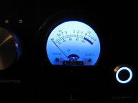
Last but not least, here are listed the remarkable features of this amplifier: independent left and right channels in a dual mono configuration; oversized transformer (400VA) for excellent regulation and current handling capability; dedicated windings for both power supply rails in each channel reducing crosstalk; Wima and Nichicon 105degºC capacitors (94.000uF in total); independent regulated low noise power supply for the preamplifier; 1% metal resistors; precise 24-step parallel attenuator (only two contact points in each position); star ground topology; source selector with distinct paths for hot and ground of the inputs; generous heat sinks; ultra silent Noctua fans with separate regulated power supply; solid chassis, feet, knobs and switch in full aluminium; gorgeous VU-meters tweaked with blue LED backlighting
that give the amplifier a dynamic and unique aesthetic by mixing modern and vintage.
GianlucaG copyright, Italy 2018
I would be very flattered if I could present my new project here, sharing this my experience among serious audio experts like you are, and maybe have here a Q&A section.
What I reported herebelow is the exact replica of my new web site where you can also enjoy some extra pic.
Website: [url=https://ggianluca.wixsite.com/opamplifier]50thanniversary[/URL]
IMPORTANT DISCLAIMER: today, 2018, manufacturer Linear Technology (LTC) is full part of Analog Device (ADI), but at the time of this design they were two distinct semiconductor companies, thus, I'm going here to mention them separately. This is an independent hobbyst project: either LTC or ADI do not have any association with this work. The information here presented is believed to be technically correct.
Conception
I named the amplifier "The 50th Anniversary" because I built it as a gift to myself for my 50th birthday.
This project comes from the heart and its conception was simple: as I am a big enthusiast in my hobby audio applications of the tonal flavour of AD826 (ADI) and LT13xx (LTC) opamp family, why not build an amplifier powerful enough to drive loudspeakers by connecting many of these chips in parallel?
How would the sonic signature be mixing them together?
It is worth mentioning that none of these video opamps was designed for audio application by their manufacturers.
Sixty chips, $5 heterogeneous ADI and LTC dual video operational amplifiers in DIP8 package, were paralleled and work in unison in the audio band by sharing
the same feedback in a master-slave configuration.
There are sixty opamps per audio channel, so 120 opamp in total, each capable of supplying 50mA individually, which provide more than 3 Ampere current when paralleled. This is adequate to drive a pair of common 8-ohm loudspeakers at 10W power with minimal distortion and excellent linearity (0.002% THD @1Wrms; 0.006% IMD; +-0.1dB over 20-20kHz; >100dB SNR, what measured by me with non-professional PC sound card).
The amplifier is built on modular stacked high-quality fibreglass prototyping boards with multiple hole connections and power rail printed patterns and the
circuit was designed with the aid of LTSpice, a freeware software circuit simulator created by LTC.
Master-slave configuration
The idea is far from to be innovative as Douglas Self in 2010 already published a superb modular power amplifier in Elektor using a massive number of cheap NE5532 opamps in a grid configuration.
Before this, many semiconductor manufacturers proved in their datasheets (OPA111, LT6020, AD826 etc..) that it is safe to put in parallel 'N' stage of opamps to reduce the relative amplifier noise and increase the output driving capability.
But "The 50 Anniversary" differentiate itself by adopting a master-slave configuration. In this design a single opamp (the "master") feeds several other
opamps (the "slaves") all placed within the master feedback loop and wired in parallel as unity gain current buffers replicating the master output voltage.
With the master feedback being wrapped around the entire net of slaves, overall accuracy is maintained.
This approach is only effective at low frequencies such as audio, where the propagation delay of the slaves is negligible with respect to the wavelength of the input signal, so that the phase shift will not cause wasted current and distortion. You may find interesting readings about this topology in few
application notes (like Intersil AN1111 or Apex AN-26) and in various datasheets (like OPA511).
Because during the model simulation LTspice displayed excessive "ringing" at the output of square-wave pulses into capacitive loads, stability was improved by adding external compensation (a shunt capacitor across the master feedback resistor) small enough to don't jeopardise the bandwidth of these fast opamps.
Different opamp sound different
"The 50 Anniversary" also combines mixed types of opamps. If you listen carefully, you may perceive some tonal changes and psychoacoustic variations when connect identical or different opamps (either in series or in parallel).
My preferred opamp is the AD826 (ADI), which is smooth, open, clean and sounds true to life in mids and voices: this opamp reproduces the best female voice I've ever heard among any op amp tested.
To me also the LTC family of fast bipolar opamps LT1355, LT1358, LT1361 and LT1364 is audio superb!
The LT1358 (LTC) is warm, bright, tonal rich and sounds forward.
The LT1364 (LTC) is dynamic, fullness, punching bass and sounds accurate.
Consequently, for the "master" amplifier it was chosen the AD826 (ADI) which alone pilots, at a gain of two, an equal mix of 59 (per channel) parallel AD826 (ADI) and LT1364 (LTC) in unity gain configuration. The pleasing parallel combination of the AD826 (ADI) with LT1364 (LTC) compensates for each other's sonic difference and exhibits the lowest listening fatiguing.
Both AD826 (50Mhz; 350 V/us) and LT1364 (70Mhz; 1000V/us) opamps exhibit outstanding technical specifications, quite difficult to find all in one sole amplifier: bipolar, single stage, handling all capacitive loads, suited to drive cables, unity gain stable, hi-current output (50ma min), wide bandwidth (>50Mhz), extremely high slew rate, low-impedance driving capability (150 ohm), class AB output stage, easy to assemble in DIP package.
Also LT1208 (LTC) has stunning sonic and technical performances, comparable to AD826 (ADI), but it has half of its current capability, hence, it was discarded.
The pre-amplifier section is made by one half of AD826 (ADI) as buffer input in series with one half of LT1358 (LTC) that provides most of the gain after the volume control: both are biased in class A by using Warren Young (tangentsoft.net/audio/) constant current source JFET cascade configuration. They have their own dedicated power supply using best-in-class complementary LT1963A/LT3015 (LTC) low noise low dropout regulators.
Chip heat dissipation
The main concern I had for this project was realizing a good cooling system because DIP packages are not intended to be mounted on heat sink at all.
Epoxy plastic is also not conductive: a DIP8 package has poor junction-to-ambient resistance, 130Cdeg/W for LT1364 (little better in AD826), hence, without cooling system, it can dissipate only one watt at 20degC ambient temperature, reaching the maximum permissible internal temperature of 150degC.
All electrical circuits dissipate some power in the form of heat. Usually both LT1364 and AD826 run very warm even in standard application because their quiescent current is elevated (7.5mA per amplifier) being hi-speed bipolar devices: higher currents mean higher slew rates on internal nodes.
Heat wears out electronic components; as described by the Arrhenius effect equation, every 10degC increase in working temperature reduces component life by half.
The power dissipation on a single chip in this design could potentially reach nearly one watt (~500mW per opamp) in worst conditions, which I select to occur driving a reactive 6 ohm load with 60deg phase angle, like could be a tough home loudspeaker.
Worst case thermal analysis
Calculations for heat dissipation in reactive loads are complex due to the phase difference between voltage and current, but Apex AN08 "Optimizing Output Power" application note helps with some 'turnkey formulas' which I have expanded here. I considered a pure sine wave signal for simplicity, which is rather cautious, since the long-term average levels for the audio tracks are much lower, depending on the type of music.
Power dissipated = PD = PI + PO where:
PI = power drawn from the power supply =
= DC power supply * AVERAGE output current + PQ =
= Vcc * 0.9 * Iout_RMS + PQ= 0.637 * Vcc * Vout_peak / |ZL|+ PQ
PQ = quiescent power supply =
= I_Quiescent * 2 * Vcc
PO = real power delivered to the load =
= Iout_RMS * Vout_RMS * cos(fi) = 0.5 * Vout_peak^2 / |ZL| * cos(fi)
|ZL| = 365 ohm, that is 6 ohm load shared among 60 opamp, plus Ro
|Ro| = 5 ohm, output resistor mandatory to prevent the parallel opamps from fighting each other
cos(fi) = cos (60deg) = 0.5
Vcc = +-15V
Vout_peak = max output swing before clipping = 13.7V
I_Quiescent = max supply current = 7.5mA
PI = 0.637 * 15 * 13.7/ 365 + PQ = 359mW + PQ
PQ = 7.4 * 2 * 15 = 222mW
PO = 0.5 * 13.7^2/ 365 * 0.5 = 129mW
PD = PI + PO = 452mW per opamp
Power dissipation per chip = 2 * PD = 904mW ~ 0.9W
Unbalanced output currents were not taken into consideration here.
Heat dissipation of 0.9W would rise the junction temperature to 117degC (=130*0.9) above ambient: because air temperature inside a cabinet might reach 47degC in summer, the chips will likely get damaged as their dies go above 150degC.
In fact, the indoor temperatures of houses in temperate zone could reach 35degC in July-August and the temperature rise inside a vented cabinet of a power amplifier rated like this, is approximately 12degC above external.
Hence, some effective cooling methods had to be adopted in this project.
Cooling methods
First the cabinet has a fully vented top cover in substitution of the standard one and is equipped with high feet: this improves natural air convection moving hot air out from the top. The temperature rise, delta T, inside the cabinet was reduced from 12deg to about 10degC above external, internally reaching 45degC in hot summer.
Second, four heat sinks were screwed onto the perfboards, each covering fifteen DIP8 chips (or 30 opamps): the purpose of the sink is to remove heat from the top surface of the chips and distribute it to the ambient. Heat sinks were selected rather large offering a natural convection thermal resistance of 1.7degC/W. But mounting them horizontally instead of vertically, like here, the natural airflow will be less effective, and the thermal resistance must be increased by about 15%, hence, to about 2degC/W.
Because fifteen devices dissipate 13.5W in total, we can expect the temperature of the heat sink (and consequently of top surfaces of the chips) to rise 27degC (=2*0.9*15) above ambient.
Given the temperature difference (per watt dissipated) between the die and the surface of a P-DIP8 device (called "Theta JC", 50degC/W for LT1364, which is in general about 2/5 of that to ambient), these chips would reach a maximum internal temperature of 117degC (=50*0.9+2*0.9*15+45) in hot summer and in worst power condition, at 0.9W.
Cooling multiple chips with a single heat sink is attractive but can create serious thermal issues: due to the differences in assembly of fifteen chips mounted in sockets, heat sink would not cover completely all chips because their top surfaces will be hardly coplanar. To prevent this, a thick (1.5 mm) and flexible thermal pad was inserted to fill any gap and ensure full contact between the heat sink and all fifteen devices.
Gap pads add extra thermal resistance between the chip and heat sink, which was minimized by using high performance silicone filled pad produced by Thermal Grizzly, ensuring a remarkable thermal conductivity of 8W/mk. This means that on top of a DIP8 surface area (60mm^2) the thermal resistance is only 3.2degC/W (=1000*1.5/ (60*8)).
Including the pad thermal resistance in above equation, junction would reach a temperature of 120degC (=50*0.9+2*0.9*15+3.2*0.9+45) when dissipating nearly one watt, which is safe but quite high, giving only 25 percent safety margin.
Because thermal performance of heat sinks can be doubled if put in airflow, internal fans were installed.
Installing silent fans
In general, adding fans to an audio amplifier is a bad idea, as their acoustical noise jeopardize sound performance at low listening levels.
This amplifier is equipped with two ultra-low-noise fans by Noctua, which run inaudible, at 9.5dB(A) combined, when underpowered.
The installed 80mm fans, which run at 7.8V at 1130 RPM generating 1.5m/s air velocity, halve the heat sink thermal resistance to 1degC/W. This gives extra
temperature margin of 13.5degC: at 0.9W dissipation the die temperature will reach 106degC (=50*0.9+1*0.9*15+3.2*0.9+45) instead of 120degC, ensuring a conservative 40% safety margin in worst power and hot ambient conditions.
It is worth then recalling that a major heat flow path from the chip to the ambient would be through the board.
In a chip there are in fact two parallel paths of heat dissipation: part of the energy is carried away from the package surface and the remaining is
conducted into the copper traces of the board through the device leads. Using sockets makes stuff worse as it adds another stage in the thermal path.
The choice to put extra layers of solder and to join large copper wires (17 AWG) along the traces, created extra paths in the board to remove heat from the chips as well as increased the current-carrying capability.
The surfaces of the four boards are mounted in the direction of the airflow of the fans and this makes the amplifier running cooler and more reliably.
During normal listening sessions the heat sinks work at 45degC (with 24degC indoor temperature), therefore each chip is dissipating 0.73W (=45-24-10/1/15) - or 367mW per opamp- and the estimated junction temperature is 84degC (=45+3.2 *0.73+ 50*0.73).
Conclusions
Due to the intrinsic nature of the project, this amplifier is of course more "a custom" at amateur level than being professional and widely marketable.
In fact, it has:
- high parts count
- high parts cost
- low power per dollar ratio
- wasting space
- critical heat dissipation
But in the end, how does this amplifier sound?
I know quality is subjective, but to me this amplifier is so exclusive, it has such a solid build quality and it sounds so vivid, crystal-clear, communicating a full and engaging soundstage, that now I enjoy music like never before.
Last but not least, here are listed the remarkable features of this amplifier: independent left and right channels in a dual mono configuration; oversized transformer (400VA) for excellent regulation and current handling capability; dedicated windings for both power supply rails in each channel reducing crosstalk; Wima and Nichicon 105degºC capacitors (94.000uF in total); independent regulated low noise power supply for the preamplifier; 1% metal resistors; precise 24-step parallel attenuator (only two contact points in each position); star ground topology; source selector with distinct paths for hot and ground of the inputs; generous heat sinks; ultra silent Noctua fans with separate regulated power supply; solid chassis, feet, knobs and switch in full aluminium; gorgeous VU-meters tweaked with blue LED backlighting
that give the amplifier a dynamic and unique aesthetic by mixing modern and vintage.
GianlucaG copyright, Italy 2018
Attachments
-
 20180119_053751.jpg68 KB · Views: 2,193
 -
 IMG_3396.JPG60.7 KB · Views: 598
 -
 20180305_055017.jpg106.1 KB · Views: 742
 -
 20180305_055000.jpg135.9 KB · Views: 796
 -
 20180305_054841.jpg93.6 KB · Views: 783
 -
 20180225_181829.jpg135.4 KB · Views: 2,080
 -
 20180211_182441.jpg175.8 KB · Views: 2,187
 -
 20180209_223730.jpg143.9 KB · Views: 2,208
 -
 20180122_214652.jpg112.5 KB · Views: 2,219
 -
 TDH_1W_8ohm.jpg61.6 KB · Views: 789
Last edited:
First, congratulations with your birthday.
Next, impressive and very thorough work. Solid craftsmanship.
Third, I like very much when people think differently than the mainstream and try to come up with new concepts.
Then, a somewhat "commercial" question: We can use Neurochrome Modulus 86 as a reference.
Modulus 86 specs:
0.000054 % (-125 dB) THD (1 W, 8 Ω, 1 kHz).
0.000088 % (-121 dB) THD (40 W, 8 Ω, 1 kHz).
0.00042 % (-108 dB) THD+N (40 W, 8 Ω, 1 kHz).
Your specs:
0.002% THD @1Wrms; 0.006% IMD; +-0.1dB over 20-20kHz; >100dB SNR
Where is it your undisputedly impressive design beats the reference (Modulus 86)?
On sound?
On efficiency?
On cost?
On physical size?
On ease of repair?
On adaptability?
Keep up the good work quality.
what make you prefer opa627?Interesting idea.
Who will be first with the OPA 627 implementation?
First, congratulations with your birthday.
Next, impressive and very thorough work. Solid craftsmanship.
Third, I like very much when people think differently than the mainstream and try to come up with new concepts.
Then, a somewhat "commercial" question: We can use Neurochrome Modulus 86 as a reference.
Modulus 86 specs:
0.000054 % (-125 dB) THD (1 W, 8 Ω, 1 kHz).
0.000088 % (-121 dB) THD (40 W, 8 Ω, 1 kHz).
0.00042 % (-108 dB) THD+N (40 W, 8 Ω, 1 kHz).
Your specs:
0.002% THD @1Wrms; 0.006% IMD; +-0.1dB over 20-20kHz; >100dB SNR
Where is it your undisputedly impressive design beats the reference (Modulus 86)?
On sound?
On efficiency?
On cost?
On physical size?
On ease of repair?
On adaptability?
Keep up the good work quality.
Hello, thank you very much for your comments.
Unfortunately I never had the opportunity to listen to those modules, but I will try to answer.
For me the best amplifier in a catalog is the one that performs:
1) the “lower listening fatigue” after a few weeks of audio sessions with different types of music. The final feeling you should have is: "nothing to add, nothing to smooth out"
2) a “constant hearing fatigue”, or even better, inversely proportional to the loudness: the listening fatigue must decrease as you increase the volume
3) a “vivid and emotional sound stage”, never flat, never boring. A "0.001% distortion" amplifier must have its own sound signature the same, which you may appreciate or not, but without being too colourful as this will fight 1)
4) a difference compared to ordinary products due to unique aesthetics and a peculiar design. As happens with luxury items, owning it must provide a unique sensory experience. The fact of having built it or, even, designed it, offers you a deeper satisfaction.
"The 50th Anniversary" wins against all the machines I have tried, owned or built (even tube amplifiers) because it is the best compromise after the previous four points.
Furthermore, I do not think the above mentioned modules exhibit the exact tonal flavour of AD826 / LT1364.
I also had the chance to try a 0.00003% distortion op-amp (LME49860) which sounds very linear but boring and flat, expecially with the voices of the singers.
As you can see from my answer, in the end, nothing has to do with technical numerical data!
Thanks
Gianluca G
Nice idea, using a chip like the AD826 in an audio application. Two years ago I applied the same chip in an other audio application (IV stage of my CD-player) where it also performed great. Comments from people who never heard this chip in an audio application were generally negative though, based on the numbers in the datasheet.
The sound qualities you descibed, I can confirm. Sound quality is not about distortion- or SN-numbers. Tube amplifiers proved that point long ago and continued to do so.
I'm curious to read about the progression of your project.
The sound qualities you descibed, I can confirm. Sound quality is not about distortion- or SN-numbers. Tube amplifiers proved that point long ago and continued to do so.
I'm curious to read about the progression of your project.
Gianluca,
An impressive construction full of aesthetics in the implementation. You are really a solid craftsman, like Enzo Ferrari was.
I thank you for your replies and understand a unique sound as a feature adding to exceptional aesthetics.
Good luck with further development of your design.
An impressive construction full of aesthetics in the implementation. You are really a solid craftsman, like Enzo Ferrari was.
I thank you for your replies and understand a unique sound as a feature adding to exceptional aesthetics.
Good luck with further development of your design.
Nicely done.
What is the loopback THD of your measuring equipment?
Hello, nothing professional...:
Hardware
Sound card: Xonar DX by ASUS
Output Signal-to-Noise Ratio (A-Weighted): 116 dB for Front-out
Input Signal-to-Noise Ratio (A-Weighted): 112dB
Output Total Harmonic Distortion + Noise at 1kHz (-3dB): 0.00056% (-105dB) for Front-out
Input Total Harmonic Distortion + Noise at 1kHz (-3dB): 0.0004% (-108dB) for Line-in
Frequency Response (-3dB, 24-bit/96kHz format): <10Hz to 48KHz
Output/Input Full-Scale Voltage: 2 Vrms (5.65 Vp-p)
Software:
Output:
Test Tone Generator (TTG) by Esser Audio, run at 16-bit/192kHz for THD and linearity curve
Multi Tone Generator (MTG) by Esser Audio for IMD
Input:
SpectraPLUS-SC Sound Card Edition by Pioneer Hill Software LLC, run at 24-bit/192kHz, 262144 FFT
LOAD:
8 Ohm 20W wirewound resistor @ 2.82V
Common stereo RCA audio cable to 3.5 mm male jack
Attachments
That's on his website: check out the first post in this thread.will you share the complete schema of this fantastic amp?
To a certain extend you're right. But since the amp consists of only a driver Opamp and multiple slave opamps in unity gain configuration, the only resistor values one need are the ones determining the overall gain, and perhaps a small capacitor to roll-off the high-end of the frequency spectrum.there is a principle schema but not a complete schema with reistors values etc..
Ok, every opamp has a resistor at the output to limit the maximum current.
there is a principle schema but not a complete schema with reistors values etc..
It should be pretty straight-forward to figure out. You can always start with Doug Self's circuit.
Personally, I'm not a fan of the master-slave setup as the slaves will add their own THD to that of the master. I would rather create one giant paralleled opamp and use one feedback loop around it. That's harder to do, but not impossible.
The output resistors are probably on the order of 0.1-1 Ω.
Tom
I am no expert, but it seems to me that what Nelson did with thousand jfets beast is way more superior, since there is no slave-master, no global feedbact to correct the distortion, just thousand times repeated perfect single stage in parallel. It cant get better that that.
Hats down.
Pitty is i do not have those jfets.
Hats down.
Pitty is i do not have those jfets.
Nice idea, using a chip like the AD826 in an audio application. Two years ago I applied the same chip in an other audio application (IV stage of my CD-player) where it also performed great. Comments from people who never heard this chip in an audio application were generally negative though, based on the numbers in the datasheet.
The sound qualities you descibed, I can confirm. Sound quality is not about distortion- or SN-numbers. Tube amplifiers proved that point long ago and continued to do so.
I'm curious to read about the progression of your project.
Thank you for your important experience!
FYI, the first idea was to build the amp exclusively with the AD826: I tried it, it was great, it had celestial mids, but it lacked some of the dynamics that is mandatory for a power amp.
Thus, I run the amp with only LT1364, which was good, but I felt nostalgic about the openness of AD826.
I've also done chip-rolling exercises in the master chip that contribute the most to the amp sound signature. Therefore, I came to the final solution of the fifty-fifty mixed types, but headed by AD826.
But, as it happens in all things, I agree that this can not please everyone, because taste is personal, overall in a listening experience.
This one...
While I was looking for your Meier parallel amplifier (really disappeared in the web, but keep searching for it...) I came across this.
https://diyaudioheaven.files.wordpress.com/2013/03/opampamp.jpg
Op-amp | DIY-Audio-Heaven

Thirty years ago, damn it, at least two decades before the Douglas Self project, probably around 1984... three decades before mine...

It looks like made from 10 x 4 quad opamps by Motorola (LM324?), that means 160 opamp per channel !
Interesting is the use of a large shared heat sink but with thermal grease, which I tested inefficient because 40 chips hand soldered will never be coplanar. But I do not think thermal pads were readily available for hobby purposes at the time...
- Status
- This old topic is closed. If you want to reopen this topic, contact a moderator using the "Report Post" button.
- Home
- Amplifiers
- Chip Amps
- Parallel opamp: an extreme audiophile amplifier made of parallel multibrand op-amps