Hi orjan,
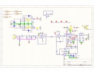
I've checked r2a. I believe its correct as on Bob's schematic fig 17.4, it goes to the negative rail. He has the -ve rail at -40V but following advice from the guys on the forum, I've reduced the rail voltages to +-28V.
What have you noticed that might be wrong?
I'm no expert.
I've checked r2a. I believe its correct as on Bob's schematic fig 17.4, it goes to the negative rail. He has the -ve rail at -40V but following advice from the guys on the forum, I've reduced the rail voltages to +-28V.
What have you noticed that might be wrong?
I'm no expert.
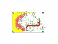
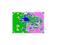
Please feel free to critique my first iteration of the Cordell Super Gainclone with Buffer, Servo and Klever Klipper. I’m sure there are many layout problems that need correction. I wanted to include the Klipper as part of the challenge but may put it on a separate board for my next attempt as per previous advice.
Problems encountered:
1) DC offset is somewhat high; 161mV with input shorted; higher than I hoped for.
2) With the input open, AC is 32mV and increases if I put my hand near C1. AC is .2mV with input shorted.
3) HUM. There is a slight amount of hum with no input. With the input shorted the hum is not present at all. When I put my hand near C1 and with nothing connected, the hum increases. When I connect my phone as an input the hum also increases. Once I choose some music to listen to and just prior to the music starting as the phone output connects, the hum goes away and it is very quiet.
Hmmm!!! I've just tried it with my Shanling music player. Doesn't appear to hum except when the input goes momentarily open. Between tracks there is no hum. It seems like the input is very sensitive to being open.
I do have an oscilloscope but am just now learning how to use it. The hum sounds just like ripple or ground loop but I can't seem to nail it down with the scope
Any layout ideas etc are much appreciated as always.
Attachments
Last edited:
I thought the DC Offset problem might be the Servo, so swapped out the chip for one of the same, an OPA2604, with similar results; tried a TLO72 and the DC Offset went straight to Zero. Not sure why that would be!
I haven't figured out the hum yet. No change there! Doesn't like to be open circuit at the input.
I haven't figured out the hum yet. No change there! Doesn't like to be open circuit at the input.
Last edited:
Why would you care about hum with the input to the amp floating? That said, 47 kΩ is a common input impedance, so you're fine there.
The relevant test is whether you have hum with the input shorted or connected to the source.
It's puzzling that you have DC offset with the OPA2604 but not with the TL072. The OPA2604 is the better device (lower offset voltage). That said, there's no need for a fancy opamp in the DC servo.
Tom
The relevant test is whether you have hum with the input shorted or connected to the source.
It's puzzling that you have DC offset with the OPA2604 but not with the TL072. The OPA2604 is the better device (lower offset voltage). That said, there's no need for a fancy opamp in the DC servo.
Tom
Ok great; its just that on the S200 I recently finished its dead quiet when not connected.
I get 3 mV AC using my multimeter with the input connected or shorted. Not sure if that is a reasonable amount?
I'll also omit the Klipper on my next board. It'll make for a much simpler layout.
I get 3 mV AC using my multimeter with the input connected or shorted. Not sure if that is a reasonable amount?
I'll also omit the Klipper on my next board. It'll make for a much simpler layout.
Last edited:
Super Gainclone based on the Cordell design WITHOUT Klever Klipper
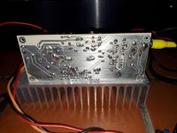
So, here is my version of the Super Gainclone based on the Cordell design WITHOUT the Klever Klipper. I finally heeded previous advice from the forum gurus and decided it's not necessary for my application; so much simpler to build and this time single sided. I've plans to do a two layer board just to compare the sound and stress myself out trying to line up the toner transfers.
As with my previous build, I decided to use a TL072 for the servo again as it gives me absolute zero DC Offset compared to other chips which give 160mV approx. For the buffer I've tried the TL072, OPA2604, NE5532 and finally the OPA2134. I may also give the LME49720 a go.
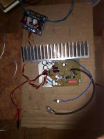
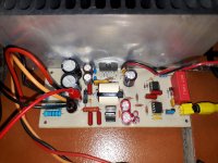
Rail voltage is set at 28V for my 4 Ohm speakers by the Q-BAIHE Sliding LT1083 adjustable power supply that I got from Lilly Maria on Amazon. They're pretty good for testing various Gainclone configurations as the output can be adjusted to suit the application. Once decided on which of my Supegainclone versions is the best sounding, I'll probably go for a more traditional Gainclone PS.
I've used 18V rail voltage for the Opamps, which I may change depending on my final Opamp choice. No heatsinks where necessary for the LM7818 /7918 as I've got some series current limiting resistors. The LM's don't even get warm. I have not included LM7818 diode protection in this version but if anyone can give me some advice as to their worth in this application, I may implement them.
Feel free to criticize. Any and all feedback is welcome.
Short video of the amp into 8 Ohm Klipsch speakers.
Cordell Super Gainclone LM3886 - YouTube
So, here is my version of the Super Gainclone based on the Cordell design WITHOUT the Klever Klipper. I finally heeded previous advice from the forum gurus and decided it's not necessary for my application; so much simpler to build and this time single sided. I've plans to do a two layer board just to compare the sound and stress myself out trying to line up the toner transfers.
As with my previous build, I decided to use a TL072 for the servo again as it gives me absolute zero DC Offset compared to other chips which give 160mV approx. For the buffer I've tried the TL072, OPA2604, NE5532 and finally the OPA2134. I may also give the LME49720 a go.
Rail voltage is set at 28V for my 4 Ohm speakers by the Q-BAIHE Sliding LT1083 adjustable power supply that I got from Lilly Maria on Amazon. They're pretty good for testing various Gainclone configurations as the output can be adjusted to suit the application. Once decided on which of my Supegainclone versions is the best sounding, I'll probably go for a more traditional Gainclone PS.
I've used 18V rail voltage for the Opamps, which I may change depending on my final Opamp choice. No heatsinks where necessary for the LM7818 /7918 as I've got some series current limiting resistors. The LM's don't even get warm. I have not included LM7818 diode protection in this version but if anyone can give me some advice as to their worth in this application, I may implement them.
Feel free to criticize. Any and all feedback is welcome.
Short video of the amp into 8 Ohm Klipsch speakers.
Cordell Super Gainclone LM3886 - YouTube
Attachments
post 8 you said :
Not really, actually you did a great job, in a few days you built 2 mono chip amps from the scratch .... Again, good job!
edit:
unfortunately I can't see the youtube video:"Video unavailable
This video contains content from WMG, who has blocked it in your country on copyright grounds."
Thanks guys.
I kind of knew what to expect as I am in fact a complete beginner!
Not really, actually you did a great job, in a few days you built 2 mono chip amps from the scratch .... Again, good job!
edit:
unfortunately I can't see the youtube video:"Video unavailable
This video contains content from WMG, who has blocked it in your country on copyright grounds."
Last edited:
As with my previous build, I decided to use a TL072 for the servo again as it gives me absolute zero DC Offset compared to other chips which give 160mV approx. For the buffer I've tried the TL072, OPA2604, NE5532 and finally the OPA2134. I may also give the LME49720 a go.
[/url]
You should use op-amp with JFET input. If you use op-anp with bipolar input, you must redesign your DC servo (R16 usually around 18K, and C9 around 47uF). Please see Ongkyo amplifier schematic that use NE5532 as DC Servo. Op-amp with bipolar input have much higher input bias current.
I think R17 value is too high.
Thanks bimo.
I was only trying the NE5532 for the input stage not for the servo. The TL072 seems to work fine as a servo regarding zero DC Offset.
Presently, I'm using the OPA2134 for the input, with the TL072 as the servo, which are both Jfet input as you recommend.
What value do you recommend I use for R17?
I was only trying the NE5532 for the input stage not for the servo. The TL072 seems to work fine as a servo regarding zero DC Offset.
Presently, I'm using the OPA2134 for the input, with the TL072 as the servo, which are both Jfet input as you recommend.
What value do you recommend I use for R17?
Thanks bimo.
I was only trying the NE5532 for the input stage not for the servo. The TL072 seems to work fine as a servo regarding zero DC Offset.
Presently, I'm using the OPA2134 for the input, with the TL072 as the servo, which are both Jfet input as you recommend.
What value do you recommend I use for R17?
I think R17 can use 100K. At op-amp DC Servo's output you can measure DC voltage and is must be below 2V (can be positive or negative). If this DC voltage too high, then you can reduce R17.
I think R17 can use 100K. At op-amp DC Servo's output you can measure DC voltage and is must be below 2V (can be positive or negative). If this DC voltage too high, then you can reduce R17.
Thanks for that bimo.
With the TL072, there is no DC Offset at all, not even 1mA. Is there a reason to lower it if there is no Offset?
Thanks for that bimo.
With the TL072, there is no DC Offset at all, not even 1mA. Is there a reason to lower it if there is no Offset?
If your op-amp DC Servo's output near to the PSU then if input DC voltage change or temperature change that can affect the DC Offset, the DC servo can not correct it.
Here you go.
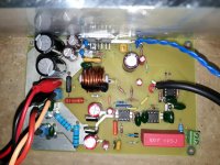
This is my SGC with No Klever Klipper! Did you want the Klipper? The board is bigger and I'm not really sure you gain much unless you intend to go close to the rails. Bob Cordell told me that it gives the amp a tuby sound.
The attached photo is of the SGC with No Klever Klipper and with NO diode protection.I have since implemented the diodes in the provided files. My reason for adding the diodes was that I had a problem with another SGC layout (not mine). I was getting +4V at the speaker output and initially suspected the Servo. Thank goodness I always check for any voltage AC or DC before powering up a new build! I eventually found that the LM7818 providing the +18V rail would not always come on line and when it did, it was only giving 0.76V (I thought it was a dry joint or bad IC socket as it was intermittent). Apparently its due to being in a dual power supply (funny how it did not affect my personal SGC layouts). Digging around on the net showed that putting a diode from the output to ground along with the appropriate caps fixes the problem. See the photo of what I found on the net. I had the caps but not the diodes. Very skeptically, I drilled a couple of holes and wedgied in a diode across the LM7818 output and was so pleased when it worked as I had already lost a lot of hair swapping out the LM's and resoldering to no aviail. I'm sure there's someone on the forum can better explain why this happens Apparently, it tends to affect the positive voltage regulators. Since then, I have thought that it would quite important to use both the diodes and speaker protection (as there's no output caps) in case a VR failed to avoid getting the DC across my beloved Elac and Kliptch speakers.
The PCB has the diodes. Up to you to implement them.
Lastly, if anyone has any layout advice I'm all ears!

This is my SGC with No Klever Klipper! Did you want the Klipper? The board is bigger and I'm not really sure you gain much unless you intend to go close to the rails. Bob Cordell told me that it gives the amp a tuby sound.
The attached photo is of the SGC with No Klever Klipper and with NO diode protection.I have since implemented the diodes in the provided files. My reason for adding the diodes was that I had a problem with another SGC layout (not mine). I was getting +4V at the speaker output and initially suspected the Servo. Thank goodness I always check for any voltage AC or DC before powering up a new build! I eventually found that the LM7818 providing the +18V rail would not always come on line and when it did, it was only giving 0.76V (I thought it was a dry joint or bad IC socket as it was intermittent). Apparently its due to being in a dual power supply (funny how it did not affect my personal SGC layouts). Digging around on the net showed that putting a diode from the output to ground along with the appropriate caps fixes the problem. See the photo of what I found on the net. I had the caps but not the diodes. Very skeptically, I drilled a couple of holes and wedgied in a diode across the LM7818 output and was so pleased when it worked as I had already lost a lot of hair swapping out the LM's and resoldering to no aviail. I'm sure there's someone on the forum can better explain why this happens
Apparently, it tends to affect the positive voltage regulators. Since then, I have thought that it would quite important to use both the diodes and speaker protection (as there's no output caps) in case a VR failed to avoid getting the DC across my beloved Elac and Kliptch speakers.The PCB has the diodes. Up to you to implement them.
Lastly, if anyone has any layout advice I'm all ears!
Attachments

Last edited:
Thanks for the kind input asuslover.
Funny that the Youtube content is banned because I'm using a Youtube video as the source! I guess it's different for each country.
Merry Christmas.
I think it is banned because of the Music in the video is Protected.
"WMG (on behalf of Rhino Warner); Warner Chappell, Kobalt Music Publishing, EMI Music Publishing, UMPG Publishing, AMRA, UMPI, and 15 Music Rights Societies"
I tried through my PIA VPN st's not location.
- Home
- Amplifiers
- Chip Amps
- Super Gainclone With Klever Klipper Based on Cordell Design