I am not sure that one pair of lm338 will be enough for a pair of lm3886 amps. On the paper is ok, 3-5v drop X 5amps =15-25 W , but not with that cooler. I would install the regulators on the lm3886 heatsink. Take a look of this :
DC-DC 7-50V to 3-45V Max 6A Adjustable Buck Regulator Block Power Supply Module 699901899761 | eBay
I never used it but might work.
DC-DC 7-50V to 3-45V Max 6A Adjustable Buck Regulator Block Power Supply Module 699901899761 | eBay
I never used it but might work.
I'm about to fabricate the final boards for my Cordell Super Gainclone.
I wanted to run my reasoning for using the NC Pins to make routing easier and also allow for wider tracks past Texas Instruments before committing myself (yes I know, I'm a caveman with my routing!).
Pins 2,4,6 connected to VEE, Pins 8 & 11 to Mute.
TI kindly provided the LM3886 Die Datasheet which I've attached for reference.
It does in fact appear from the datasheet that the NC Pins have no internal connection at all.
As previously mentioned, the LM4780 datasheet on page 22 “LM4780 REFERENCE BOARD ARTWORK“ also has NC pins connected to adjacent pins.
I'm going to go ahead and use them at my risk. If anyone decides to use them based on my findings, it is at their risk
Hope this is of use to any other DIY cavemen.
Attachments
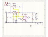
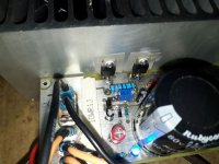
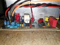
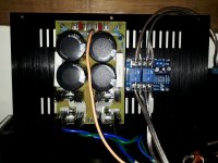
Dual positive regulated power supply for my Super Gainclone in an attempt to get round the problem of the voltage drop I was experiencing at high volumes.
I didn’t want to use a regulated supply; unfortunately my transformer output is too high for my 4 Ohm speakers so hence the complication.
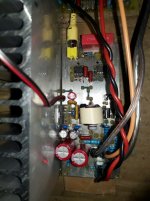
To try and get round the voltage drop, I paralleled two LM388’s on each rail using 0.1 Ohm 10W output resistors. The supply has the same soft start circuit and takes 10 seconds to reach 26V using a 10uF capacitor and 33k resistor along with the A1015 transistor. Don't think I really need the soft start but it's all part of the learning process!
I didn’t want to get overcomplicated with an opamp controlling the LM338’s and was concerned that load sharing would be a problem. So far, they appear to be behaving with just the 0.1 Ohm resistors; hopefully they’ll continue that way! The voltage drop seems to have gone but I’ve still to connect a preamp with a higher output than my phone for some more stressful testing.
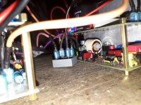
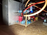
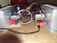
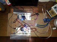
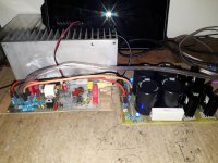
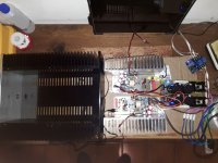
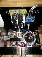
Due to the rather small chassis that arrived I had to rethink the mounting of the power supplies (they were no way going to fit). The heatsinks are massive but the space in between them is really narrow, so it’s going to be a squeeze.
asuslover recommended I mount the LM338’s on the same heatsinks as the LM3886’s (thanks for that asuslover!). The only option I saw, was to mount the power supplies in two halves over the SGC’s, positive rail on one sink and negative on the other. I’ve done a mock-up of the planned mounting on some old heatsinks. Seems to work, just a pain to connect things up! You have to decide which power supply will be the positive and negative rail; very easy to miss connect things and stuff all your efforts!
I’ve left a YouTube link in case anyone is interested in the sound. Same Metallica song that I love so much but good for comparing results between builds.
YouTube
Criticism, comments or advice more than welcome!
I didn’t want to use a regulated supply; unfortunately my transformer output is too high for my 4 Ohm speakers so hence the complication.
To try and get round the voltage drop, I paralleled two LM388’s on each rail using 0.1 Ohm 10W output resistors. The supply has the same soft start circuit and takes 10 seconds to reach 26V using a 10uF capacitor and 33k resistor along with the A1015 transistor. Don't think I really need the soft start but it's all part of the learning process!
I didn’t want to get overcomplicated with an opamp controlling the LM338’s and was concerned that load sharing would be a problem. So far, they appear to be behaving with just the 0.1 Ohm resistors; hopefully they’ll continue that way! The voltage drop seems to have gone but I’ve still to connect a preamp with a higher output than my phone for some more stressful testing.
Due to the rather small chassis that arrived I had to rethink the mounting of the power supplies (they were no way going to fit). The heatsinks are massive but the space in between them is really narrow, so it’s going to be a squeeze.
asuslover recommended I mount the LM338’s on the same heatsinks as the LM3886’s (thanks for that asuslover!). The only option I saw, was to mount the power supplies in two halves over the SGC’s, positive rail on one sink and negative on the other. I’ve done a mock-up of the planned mounting on some old heatsinks. Seems to work, just a pain to connect things up! You have to decide which power supply will be the positive and negative rail; very easy to miss connect things and stuff all your efforts!
I’ve left a YouTube link in case anyone is interested in the sound. Same Metallica song that I love so much but good for comparing results between builds.
YouTube
Criticism, comments or advice more than welcome!
Attachments
-
 Parllel LM338 Positive Power Supply.jpg181.4 KB · Views: 308
 -
 20190204_232738_1.jpg386.9 KB · Views: 172
 -
 20190204_232724_1.jpg382.7 KB · Views: 628
 -
 20190204_232625_1.jpg420.6 KB · Views: 637
 -
 20190204_232410_1.jpg301.9 KB · Views: 633
 -
 20190204_232400_1.jpg435.7 KB · Views: 644
 -
 20190204_232349_1.jpg367.7 KB · Views: 673
Ref the parallel LM338's.
Using just ballast resistors, I found the load sharing to be OK at low levels but not high.
It would appear that much higher value resistors are needed to make this option work at higher levels of power without an opamp if at all.
I was hoping not to have to use buck converters or worse still, buy another transformer to be able to use my 4 Ohm Elacs with the SGC.
This is going to be the final iteration of my Cordell Super Gainclone. Two sided is my final choice as all advice to date has been to go this route and I now concur after trying both single and two sided versions of exactly the same circuit even with my amateur layout!
I was hoping not to hear a difference between my single and two sided boards with no input connected (I now know it shouldn’t matter but I don’t like hum with nothing connected and to my surprise, this version is silent). With the input shorted, it doesn’t matter how close I get to the speaker, there is nothing to hear.
I’ve used a ferrite bead on the first 470 Ohm input resistor; not sure how much RF will be rejected though! I moved the RCA input to the back of the board and inboard somewhat as I’m going to use premade right angled RCA cables/ connectors to save space in my rather small chassis.
The entire top of the board is main ground, so had to use some vias (God I hate using vias!). The left side bottom of the board is VEE, then VCC, Speaker Out, silent ground on the right hand side of the board joining the main ground at R1, +-18V at the bottom of the board.
The Inductor is the same as previous using around one meter of 16-gauge wire; 7 wraps then 6 on a cardboard tube then held in place inside a gash piece of PVC to give around 2.2uH. Bob Cordells’ design requires 3.3uH but I just can’t get enough wire wrapped. I followed the SC200 amp instructions to make the inductor.
I’ve used an OPA2134 for the buffer and inverter this time, with a TLO71 for the servo (DC offset is around 2mA). The single sided boards tried to pick up radio stations when I used the OPA2134 but the two sided board is dead quiet, so I’ll use it instead of the OPA2604.
I’m still stuck with the slightly high supply voltage of 31.7 for my 4 Ohm speakers using the CRC Power Supply (Class A amplifier) I’ve changed the CRC resistors from 0 .1 Ohm 10W to 0.5 Ohm 2x10W piggybacked each side in an attempt to drop the voltage to 28V for my 4 Ohm speakers at higher power settings. It seems to work when simulated but I’ll see how hot the chips with this setup once they’re in the chassis on their massive heatsinks.
One more double sided board to make, then its chassis time again!
Attachments

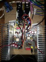
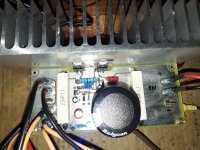
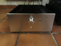
Stereo Cordell Super Gainclone with Double Sided PCB, 28V Rails, in Chassis First Test With 8 Ohm Klipsch and Preamp input.
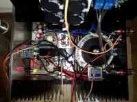
Quite hard to get all the gubbins into the chassis; my fault during chassis selection online! I'll double check the inside dimensions more thoroughly before purchasing next time. The heatsinks are real monsters but theres not much room inside the case iteslf. I used the top panel for the CRC Power Supply (Class A amplifier) as well as the speaker protection. The small tranny is for the speaker protection. During the final assembly, I did the twisted pair thing with as many of the power carrying cables as possible. Not easy with such limited space.
I'd like to thank everyone who spent some of their valuable time and gave me the help I sorely needed in order to be able to complete this rather long winded project
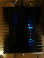
So far this little amp sounds really great; no hum, completely silent! Tomorrow I'll see what happens into my 4 Ohm Elacs.
If interested, there's a Youtube video! Yes thats right Metallica again. YouTube
Quite hard to get all the gubbins into the chassis; my fault during chassis selection online! I'll double check the inside dimensions more thoroughly before purchasing next time. The heatsinks are real monsters but theres not much room inside the case iteslf. I used the top panel for the CRC Power Supply (Class A amplifier) as well as the speaker protection. The small tranny is for the speaker protection. During the final assembly, I did the twisted pair thing with as many of the power carrying cables as possible. Not easy with such limited space.
I'd like to thank everyone who spent some of their valuable time and gave me the help I sorely needed in order to be able to complete this rather long winded project
So far this little amp sounds really great; no hum, completely silent! Tomorrow I'll see what happens into my 4 Ohm Elacs.
If interested, there's a Youtube video! Yes thats right Metallica again. YouTube
Attachments
Last edited:
PDF Prinouts for my Cordell Super Gainclone 2 sided board.
PDF Prinouts for my Cordell Super Gainclone 2 sided board.
This amp definitely works well. I have built 6 to date, finally arriving at this version; however, If you wish to use the files, it is at your own risk!
I am always open to constructive criticism and can still make changes to the layout or component choices.
-A5 size paper.
-For toner transfer use the mirrored file for the top side.
-Most pads with no connection on a layer are removed to avoid alignment problems. Drill from the side with a pad or hole.
-Few vias are required at the top Ground connections i.e. one each at the electrolytic caps and one at U5 pin3 (you can get away without vias with careful soldering).
-Most other top ground connections can be soldered from the top i.e. the remaining caps, the 18v LM7XXX and the LM3886 ground.
-I opted for an OPA2134 for the buffer /Inverter and a TLO71 for the Servo but there are many other options.
-I put a small ferrite bead on R4 for RF interference.
PDF Prinouts for my Cordell Super Gainclone 2 sided board.
This amp definitely works well. I have built 6 to date, finally arriving at this version; however, If you wish to use the files, it is at your own risk!
I am always open to constructive criticism
and can still make changes to the layout or component choices.-A5 size paper.
-For toner transfer use the mirrored file for the top side.
-Most pads with no connection on a layer are removed to avoid alignment problems. Drill from the side with a pad or hole.
-Few vias are required at the top Ground connections i.e. one each at the electrolytic caps and one at U5 pin3 (you can get away without vias with careful soldering).
-Most other top ground connections can be soldered from the top i.e. the remaining caps, the 18v LM7XXX and the LM3886 ground.
-I opted for an OPA2134 for the buffer /Inverter and a TLO71 for the Servo but there are many other options.
-I put a small ferrite bead on R4 for RF interference.
Attachments
Last edited:
- Home
- Amplifiers
- Chip Amps
- Super Gainclone With Klever Klipper Based on Cordell Design