Hi MexMike,
Thank you very much. Thanks for the tip on the L7818 latch-up.
I'm very fond of tube amps, but I don't know how important the Klever Klipper is. Perhaps I can tack it up on a separate board and try it.
Which version of the board do you prefer, the polygons or regular?
Also, are you implementing the mute function?
I was going to add a cheap Ebay UPC1237 delay/dc protection board.
Thank you again and best wishes
Hi MexMike,
Thank you very much. Thanks for the tip on the L7818 latch-up.
I'm very fond of tube amps, but I don't know how important the Klever Klipper is. Perhaps I can tack it up on a separate board and try it.
Which version of the board do you prefer, the polygons or regular?
Also, are you implementing the mute function?
I was going to add a cheap Ebay UPC1237 delay/dc protection board.
Thank you again and best wishes
I've uploaded a new video of the SGC. It's the same song from Youtube as my other two videos which haven't been banned yet. Maybe good for comparison with my DIY SC200 which I love dearly. Why would Youtube ban a video from its own site? Sounds daft but maybe I'm missing something!
YouTube
I made the mistake of using a Log potentiometer for the Klipper, so nothing happens until the last bit of rotation. I wanted to see if it would be a good amp to use with guitar; adjusting the klipper way ahead of rail voltage to suit. With normal music input, it sounds like the signal is getting attenuated to me, so I decided to forgo it. Bob Cordell has a 1k resistor R1 at the Klipper. It just appears to attenuate the signal, so I omitted it to keep the total resistance of 10.1k at that point in the circuit the same, with or without Klipper. You could maybe use a header there and switch on and off as you choose.
I think the polygons are better; less copper to etch. Just be really carefull of the traces at the LM3886 and some of the smaller caps, they are close. Maybe the gurus can maybe give some input regarding the two versions of my layout, as I am not an expert. The printout is for laser toner obviously.
For the inductor, I went for as close to the 3.3uH as I could get; somewhere near 2.2uH. I used the same inductor design as per the SC200 article. This is basically 1 meter of 1.25mm dia copper wound on a 10mm ID bobbin, 8mm wide. First 7 wraps, then 6.5 wraps. I found a cardboard tube exactly that diameter, did the first 7 wraps and then poured a little superglue over the coils. let it dry, unstuck my fingers and then gingerly did the second 6.5 wraps. You can omit the finger sticking part if you like
 The 10 Ohm 5W resistor fit perfectly inside the tube. I then had a gash piece of plastic tube that fit exactly over the inductor wraps, followed by more superglue just to keep the inductor nice and solid.
I always use the mute with a switch as I'm too chicken to risk my speakers when testing. I first use a tiny PC speaker before using my Elac and I like to have the switch close by in case something goes tits! I also bought some cheap speaker protection which work great! You can use the 15-18V from the onboard power if you want but I prefer to use a transformer with the additional low voltage windings. for that.
Hope this helps.
Last edited:
Wow! That's great that you posted videos comparing the two amps. Which one do you prefer so far?
My speakers are homemade Peerless-Scanspeak MTM. The impedance get down to as low as 3 ohms, so I'm a little concerned about stressing an amp. I currently use a tube SE 845 and Class-D TK2050. The 845 is magic.
Thank you for the details on managing without the Klipper and about the inductor.
My speakers are homemade Peerless-Scanspeak MTM. The impedance get down to as low as 3 ohms, so I'm a little concerned about stressing an amp. I currently use a tube SE 845 and Class-D TK2050. The 845 is magic.
Thank you for the details on managing without the Klipper and about the inductor.
Wow! That's great that you posted videos comparing the two amps. Which one do you prefer so far?
My speakers are homemade Peerless-Scanspeak MTM. The impedance get down to as low as 3 ohms, so I'm a little concerned about stressing an amp. I currently use a tube SE 845 and Class-D TK2050. The 845 is magic.
Thank you for the details on managing without the Klipper and about the inductor.
The problem with building something, is that it becomes your baby and it’s a little hard to be objective.
The SC200 is probably one of the best amps of the "Blameless" ilk as it has gone through many iterations. I believe it started out as the Studio 350 or something but not sure. I love it with a passion. It sounds amazing but I didn't design the layout or make the PCB, as they are from the wonderful folk down under at Silicon Chip magazine; really cheap boards and so well made. I had a slight problem with the SC200 build after frying a few parts due to removing a test lead with power on. Thanks to Bao, John and Nicholas at SC Magazine all is now well and I love the amp for not going into the bin but into a massive Aly chassis in my living room.
The SGC on the other hand is something I wanted to build from scratch. Thanks to the kind input from the guys in this thread and much internet delving, I managed to "join the dots" and produce something that makes sound. Whether it is a good sound to anyone else is not for me to decide but my well bashed ears from years in helicopter maintenance tells me that both amps are superb. One does the business through several transistors and the other through an IC. With both amps, the Youtube song that I play through them on Youtube, says it all! (love this Metallica song) At the beginning of the song you listen to the soft guitar and sit a little too close to the speaker, then suddenly the base kicks in and you realise how high you have the volume turned up and have to back away. So solid clear and crisp in every way.
I’ll be doing my own SC200 at some point, bought the copper vias from a nice chap in Greece, just need to finish my version of the layout.
So, to finally answer your question, I don’t have a preference. I luv em bof and muchly so!
As everyone here says. Keep the rail voltage low on the LM3886 for low Ohm speakers. Not sure if the LM3886 will be cool with 3 Ohms. The SC200 is guaranteed stable down to 4 Ohms. Make two more speakers and put them in series!
Good luck and Seasons Greetings to you and Yours.
Last edited:
I've uploaded one more video, this time with a preamp as input to give a better idea of the sound. Hope it doesn't get banned! I want to let it get good and hot into my 4 Ohm Elac speaker, with 28V rails and 18V on the IC's. The amp VR LM7818/9's now have the diode protection as per my schematic, two on each side; seems to work! I know I've got the rail voltage on max for 4 Ohm speakers.
YouTube
YouTube
Hi MexMike,
Thank you very much. Thanks for the tip on the L7818 latch-up.
I'm very fond of tube amps, but I don't know how important the Klever Klipper is. Perhaps I can tack it up on a separate board and try it.
Which version of the board do you prefer, the polygons or regular?
Also, are you implementing the mute function?
I was going to add a cheap Ebay UPC1237 delay/dc protection board.
Thank you again and best wishes
It may be also be worth considering changing the LM7818/7918 capacitor values to coincide with the datasheet, which shows 0.33uF and 2.2uF at the input and 0.1uF and 1uF at the output. I've also been told that 0.1uF should be at all pos and neg input and output positions but don't really know what is best. I guess the datasheet always gives the best advice.
Hi MexMike,
I noticed that you are using the metal-backed LM3886T with mica insulators. What size is the insulator? Do you have a source?
I have been searching the Google with nothing clear. Mouser, Digikey, etc haven't been too helpful.
Thank you again - ziffel
Farnell part No 520-238 fit the Lm3886T. Ive used them in several Neurochrome audio builds.
Hi MexMike,
I noticed that you are using the metal-backed LM3886T with mica insulators. What size is the insulator? Do you have a source?
I have been searching the Google with nothing clear. Mouser, Digikey, etc haven't been too helpful.
Thank you again - ziffel
Actually, I use the mica insulators for the TO-3. I also could not source the exact mica insulators easily.
Trying to follow tomchr, 00940 and other kind contributors to my betterment, I have completed one more version of the Cordell SGC; again without the Klipper and this time with the recommended two layers. I managed to use only four through hole vias (keep dropping the little buggers).
Bobs circuit uses a OPA2604 for the Servo, but due to the lower DC Offset, I originally went for the TL072. This time I swapped out the TL072 for a TL071 due to the unused portion of the IC. The DC Offset is still low at 3mV.
As usual I had major problems trying to keep the transfer aligned going through the laminator; not sure what I need to do to improve my alignment! I definitely need to improve how I feed the board through on the second pass. Double sided PCBs amongs other things are definitely my nemesis.
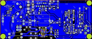
The Ground Plane is on top. The bottom layer has VCC, VEE on the LH side, with the Quiet Ground on the RH side of the board joining the Top layer at R1. I also added a couple of rail voltage indicator LEDs.
My ears can’t tell the difference between the single and two layer versions (maybe both are equally bad layouts ha ha!).
Please feel free to criticize. Hopefully I’m getting closer to a final version and can move on to my next project.
Thanks in advance for any input.
Bobs circuit uses a OPA2604 for the Servo, but due to the lower DC Offset, I originally went for the TL072. This time I swapped out the TL072 for a TL071 due to the unused portion of the IC. The DC Offset is still low at 3mV.
As usual I had major problems trying to keep the transfer aligned going through the laminator; not sure what I need to do to improve my alignment! I definitely need to improve how I feed the board through on the second pass. Double sided PCBs amongs other things are definitely my nemesis.
The Ground Plane is on top. The bottom layer has VCC, VEE on the LH side, with the Quiet Ground on the RH side of the board joining the Top layer at R1. I also added a couple of rail voltage indicator LEDs.
My ears can’t tell the difference between the single and two layer versions (maybe both are equally bad layouts ha ha!).
Please feel free to criticize. Hopefully I’m getting closer to a final version and can move on to my next project.
Thanks in advance for any input.
Attachments
I wanted to do my own DIY PCB, power supply, for my Cordell Super Gainclone project and found the CRC Power Supply in the thread started by Project16 with a mega contribution by Prasi!
CRC Power Supply (Class A amplifier)
I pretty much worked from the exact schematic designed by Project16. I went for the diode caps version and gleaned enough info from the CRC Power Supply PCB images uploaded by and designed by Prasi, to get a rough idea of the layout. Thanks for the hard work Project16 and Prasi you made my bit much easier!
I've uploaded a couple of more detailed photos of the PSU in the previously mentioned thread. It works really well with my SGC; No hum that my battered ears can detect.
If your looking for a PSU PCB and don't want to make the PCB yourself, get in touch with Prasi.
Now I'm just waiting for the chassis from China and still trying to figure whether to go single or dual layer SGC. They both sound the same to me.
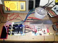
The multi-meter is showing DC offset whilst listening to some music by the way.
CRC Power Supply (Class A amplifier)
I pretty much worked from the exact schematic designed by Project16. I went for the diode caps version and gleaned enough info from the CRC Power Supply PCB images uploaded by and designed by Prasi, to get a rough idea of the layout. Thanks for the hard work Project16 and Prasi you made my bit much easier!
I've uploaded a couple of more detailed photos of the PSU in the previously mentioned thread. It works really well with my SGC; No hum that my battered ears can detect.
If your looking for a PSU PCB and don't want to make the PCB yourself, get in touch with Prasi.
Now I'm just waiting for the chassis from China and still trying to figure whether to go single or dual layer SGC. They both sound the same to me.
The multi-meter is showing DC offset whilst listening to some music by the way.
Attachments
I currently use toner transfer with this modified Apache laminator purchased from ebay...
All steel laminator modified for automatic single-pass PCB toner transfer. | eBay
It does a great job and works as advertised; 6 minutes to transfer without intervention. I do however have problems lining up the second side of the board. How do you get down to 0.25mm error between sides?
Do you do one side at a time or both at once?
My problem is always with aligning the second side!
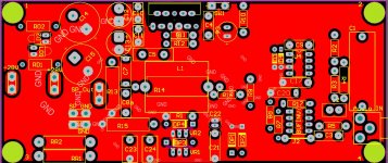
Cordell Super Gainclone (without Klever Klipper) PDF Prinouts for my two layer board.
-Board Size is 152.048mm by 64.262mm
-Top layer mirrored for toner transfer.
-Pads on layers with no connection have been removed to avoid alignment problems.
-It is my understanding that the NC pins are truly NC and for that reason, I have used them when they get in the way of a track. I found some evidence here:
Simple LM4780 question... and decided that the same may apply to the LM3886 and just went for it. Everything works so it is what it is.
-Paper size is A5.
-The traces at VCC, VEE and Speaker Out are close and need careful checking BEFORE removing toner whilst etching.
-If flux is used for soldering it MUST be thoroughly removed from the board before power up as appears to become conductive after some time. I'm not sure if I've got my facts right but I've had problems in the past that made me think that a board had failed, only to find that cleaning solved the problem.
Its still a work in progress and there is much room for improvement
Attachments
-
Altium Cordell SGC 2 Layer TLO71 Servo TOP.pdf21.3 KB · Views: 105
-
Altium Cordell SGC 2 Layer TLO71 Servo TOP Mirror.pdf21.2 KB · Views: 84
-
Altium Cordell SGC 2 Layer TLO71 Servo BOT.pdf31.4 KB · Views: 107
-
Altium Cordell SGC 2 Layer TLO71 Servo TOP SILK.pdf29.9 KB · Views: 96
-
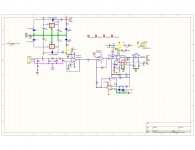 Altium Cordell SGC 2 Layer TLO71 Servo SCH.jpg190.7 KB · Views: 254
Last edited:
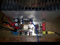
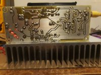
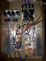
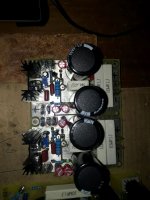
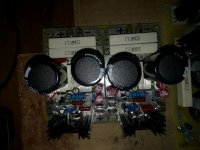
Some photos of my Cordell Super Gainclones. One is single and the other dual layer.
I’ve shown two power supplies in the photos. The reason being is due to a slight calculation hiccup on my part when ordering the transformer. The manufacturers spec for the Antek Toroid AS-3222 300VA of 22V output for 115V input would have been fine for my 4 Ohm speakers, the rectified voltage would have been at the top of the range at around 30V (ref tomchr). Unfortunately, I forgot to take into account that my local voltage is a little higher than US voltage at around 129V, so I get around 34V rectified instead of the 30V that I need from the CRC Power Supply (Class A amplifier).
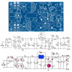
I thought I could use a regulated power supply to drop the voltage. I used the Ebay “Low Noise Distortion Power Supply PCB LM317 LT1083 LM1085 LM350 Supply Bare Kit” (diagram attached) as a template for two side by side positive supplies. I omitted the fuses to save space as the chassis will have its fuse! The supply works fine; zero ripple, slow start and easy to adjust. The only caveat is that I used LM338’s. At max volume, the rail voltage drops to 26V. Both the CRC and regulated power supplies use 0.1 Ohm resistors in series (Dohh!!! I do have one more 0.235 Ohm in the regulated supply. The CRC Power Supply, of course, doesn’t bat an eyelid! I could piggyback two LM338’s but the real estate in my new chassis is severely limited so that’s out of the question.
Next stop will be Chinese LT1083’s. One of the suppliers at aliexpress seems to get good customer reviews for their chips, so I’ll give them a chance before I buy another transformer!
I might bypass the input filter resistors on the LM338’s and see if the the difference in voltage drop is workable. I don’t think it’ll affect the LM3886’s too much.
I do realise that 3V is required for “Line regulation” so may play a part in my problem. I’d also thought that the voltage drop could be put down to the LM338’s reaching their current limits trying to run two LM3886’s but am really not sure of the cause. I guess I should measure the drop directly across the resistors as well.
Any other reason for voltage drop would be much appreciated.
I’ve shown two power supplies in the photos. The reason being is due to a slight calculation hiccup on my part when ordering the transformer. The manufacturers spec for the Antek Toroid AS-3222 300VA of 22V output for 115V input would have been fine for my 4 Ohm speakers, the rectified voltage would have been at the top of the range at around 30V (ref tomchr). Unfortunately, I forgot to take into account that my local voltage is a little higher than US voltage at around 129V, so I get around 34V rectified instead of the 30V that I need from the CRC Power Supply (Class A amplifier).
I thought I could use a regulated power supply to drop the voltage. I used the Ebay “Low Noise Distortion Power Supply PCB LM317 LT1083 LM1085 LM350 Supply Bare Kit” (diagram attached) as a template for two side by side positive supplies. I omitted the fuses to save space as the chassis will have its fuse! The supply works fine; zero ripple, slow start and easy to adjust. The only caveat is that I used LM338’s. At max volume, the rail voltage drops to 26V. Both the CRC and regulated power supplies use 0.1 Ohm resistors in series (Dohh!!! I do have one more 0.235 Ohm in the regulated supply. The CRC Power Supply, of course, doesn’t bat an eyelid! I could piggyback two LM338’s but the real estate in my new chassis is severely limited so that’s out of the question.
Next stop will be Chinese LT1083’s. One of the suppliers at aliexpress seems to get good customer reviews for their chips, so I’ll give them a chance before I buy another transformer!
I might bypass the input filter resistors on the LM338’s and see if the the difference in voltage drop is workable. I don’t think it’ll affect the LM3886’s too much.
I do realise that 3V is required for “Line regulation” so may play a part in my problem. I’d also thought that the voltage drop could be put down to the LM338’s reaching their current limits trying to run two LM3886’s but am really not sure of the cause. I guess I should measure the drop directly across the resistors as well.
Any other reason for voltage drop would be much appreciated.
Attachments
Last edited:
Ive just simmed the circuit. It looks like the resistors are dropping too much voltage to leave room for regulation. If that is the case, I'll remove the resistors and use 25-28V for the LM3886's into 4 ohm.
I'll do a physical tomorrow. Hopefully that's all it is!
I'll do a physical tomorrow. Hopefully that's all it is!
Last edited:
Thanks for that asuslover.
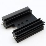
My only concern was the regulated voltage drop from 28 to 26V at high power. Hopefully removing the resistors will solve that. I'll try removing the two 0.1 Ohm rail resistors first. If the LM338's start getting too hot at high power, then I'll have to look at the power dissipation. Do heatsinks I've used in the photo are big enough! Dims are 40l x 38 x 13mm
Lastly. Is one pair of LM388T sufficient for powering two LM3886's, or do I need one set for each amp?
Thanks again. I appreciate the much needed advice
Attachments
- Home
- Amplifiers
- Chip Amps
- Super Gainclone With Klever Klipper Based on Cordell Design