IIRC the chip and transistors tended to die together if/when something went wrong. See post #11.
Mooly's subtle humor ... " You should find the TDA2030 does an admirable job of protecting the fuse. That was always my experience of them." ... perhaps needs a less-sophisticated translation: "If something goes wrong, TDA2030 goes poof before the fuse had a chance to blow up".
Mooly's subtle humor ... " You should find the TDA2030 does an admirable job of protecting the fuse. That was always my experience of them." ... perhaps needs a less-sophisticated translation: "If something goes wrong, TDA2030 goes poof before the fuse had a chance to blow up".
there are some commercial designs with chipamps and booster transistors.......
iirc linn majik , linn chakra (tda7293 .....).... etc.
if you search the diy........
TDA7293/TDA7294 - by which commercial integrated Stereo Amps in use ?
iirc linn majik , linn chakra (tda7293 .....).... etc.
if you search the diy........
TDA7293/TDA7294 - by which commercial integrated Stereo Amps in use ?
Good evening everyone!
And again a question about the TDA2030 + transistors.
I thought that according to the scheme, the resistors from which the signal is fed to the base of the transistors can have a spread of resistances, the voltage drop across the transitions of the transistors is also different. I have 0.515 and 0.542 V. I decided to pick up the resistance of the resistors in order to the transistors will open at the same current. But measuring low-resistance resistors with a multimeter is mindless, so I took a 9 volt PSU, a resistance of 40 ohms and eight resistors at 0.75 ohm (1.5 ohms resistors were not in the store) installed in series. I measured the total resistance of the circuit, applied power to this circuit, measured the voltage, calculated the circuit current, then measured the voltage drop across each 0.75 Ohm resistor and calculated their actual resistances. And at last I have selected the most optimal resistance for each transistor.
It took some time and effort. Is there a positive sense in this selection of resistors or it was in vane?
And more, is it possible to consider the above-described method of measuring the resistance of a small quantity reliable?
Kshishtoff - it actually doesn't matter. The conduction point of the transistor is not a digital bit that switches on and off, there is a ramp (admittedly, a steep transition - but the transistor does conduct a little bit before being switched on fully). This has ramifications on (for example) V/I limiters in output stages, where you can get some artificial limiting before the actual set threshold.
And even if you did hand-match resistor to the actual Vbe of the transistor, it serves little extra purpose because for the time that the transistor is not conducting, the TDA chip is. So you do not really have any benefit of keeping the top and bottom halves identical. Unless of course all you do is play square and sine waves and even then I'm not sure what the point would be.
I hate these sort of circuits, they tend to be extremely flaky and unpredictable at the best of times. You do need lots of bandwidth limiting at both ends and some zobels on the transistors to keep them stable. All Class AB amps put a lot of junk into the power rails and using these rails to switch a power booster is not a great idea.
To answer your other question, for a low value resistor you should have a precise CCS - say 100mA - and measure the voltage across the resistor, and use Ohm's law. This is how we measure 5% emitter resistors down to 1% matches. A CCS of 100mA can be built with a 5-9V wallwart, an LM317 and a single (precise) resistor. Ordinarily though, in user-based applications requiring a very low value resistor, the actual value of the resistor is not critical. Measuring instruments require precise current shunts - 0.1% or better is preferred, but for almost any audio applications, 5% variation should be acceptable.
Thanks for the answer. OK, I understand, that schematic is unsuccessful. I just had a sad experience with TDA2050 and 4 Ohm load. It's broken. Probably from overloading. Although the circuit was fed from only 36 V. So I just need a reliable circuit for 4 ohm.I hate these sort of circuits, they tend to be extremely flaky and unpredictable at the best of times. You do need lots of bandwidth limiting at both ends and some zobels on the transistors to keep them stable. All Class AB amps put a lot of junk into the power rails and using these rails to switch a power booster is not a great idea.
There is another option with two TDA2030 in parallel, or change the circuit and send a signal to the transistors from the output of the IC instead of from the power rails.
I'll lay out the schemes tomorrow.
The output sense circuit works, but the resistor wastes a lot of power - unless it's a very high value and then the chip is basically useless as the transistors cut in early. My vote would be for parallel operation but do understand that the 20xx line are very basic car radio and TV set chips from the 80s, so don't expect to get lots of clean, reliable power out of them. Plus they've been obsolete so long that every single device out there is either factory reject or cloned in a back alley of China.
They are a lot of fun to work with because they're so simple to put together - but for a reliable 4 ohm-capable amplifier that will go nice and loud I really would go for the LM3886, two chips in parallel per channel. That sort of amplifier is almost indestructible when built properly (I still have my Peter Daniel LM4780 kits from 2004!) and sounds far ahead of this lot.
They are a lot of fun to work with because they're so simple to put together - but for a reliable 4 ohm-capable amplifier that will go nice and loud I really would go for the LM3886, two chips in parallel per channel. That sort of amplifier is almost indestructible when built properly (I still have my Peter Daniel LM4780 kits from 2004!) and sounds far ahead of this lot.
Don't spread "fake news". TDA2030(A) are still current production ICs. As are some other TDA20xx series.
UNISONIC TECHNOLOGIES CO.,LTD
http://www.unisonic.com.tw/datasheet/TDA2030A.pdf
Unisonic Technologies(UTC)
http://www.utc-ic.com/2011/0922/TDA2030A.html
With this current-dumping circuit topology, you basically need to assure that transistors are safely turned off at idle, and go into conduction at some safe "sweet spot", and get out of conduction precisely when they must do so.
My suggestion was to drop the sensing resistors to cca 1 Ohm (so cca 600-700mA to turn-on). My other suggestion would be to do a worst-case "smoke test" at a lower voltage (say 30V); in other words to abuse the (sacrificial) amp with anything you can throw at it and take notes of the failure modes.
You can then make an informed decision if this amp is suitable for you or not.
As for the LM3886 and the like, I can say that as long as I do not have a powerful enough acoustics, I do not see any reason to do such schemes. And as soon as they appear, I'll make an transistor amplifier.
My attempts to make an amplifier with TDA are just for fun, instead of watching TV and to learn a little about electronics.
And in fact, the TDA2030 is an excellent chip, because of its price, availability and capabilities.
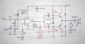
And I have some questions again")
What can you say about this scheme? It's a simple improved class B amp. I think it should work well enough. But I do not quite understand what value of the resistors to take in the bias circuit of the transistors. And how should I include the isolation capacitors between the chip and the transistors? Where should I put a positive plate? To the chip or to the transistors?
My attempts to make an amplifier with TDA are just for fun, instead of watching TV and to learn a little about electronics.
And in fact, the TDA2030 is an excellent chip, because of its price, availability and capabilities.
And I have some questions again
What can you say about this scheme? It's a simple improved class B amp. I think it should work well enough. But I do not quite understand what value of the resistors to take in the bias circuit of the transistors. And how should I include the isolation capacitors between the chip and the transistors? Where should I put a positive plate? To the chip or to the transistors?
Attachments
Don't spread "fake news". TDA2030(A) are still current production ICs. As are some other TDA20xx series.
Not from the original manufacturer. The $64k question is which if any copies out there are any good. There have been cases documented here of TDA2030 fakes that *work* but have obvious undersized dies in the x-rays.
I have found some NOS TDA2002's that seem to be perfectly good. They had the old SGS logo on them and haven't blown up yet. Can't run those at a high enough Vcc to make the extra transistors worthwhile.
I built theTDA2030 circuit with output transistors from a Elektor 300 circuits book powered it with a 40 volt dc supply and used it on a EC SX300 which I remember it was jumping around the workshop. I should imagine you could use LM1875 and crank the voltage up to 50 volt I have seen a circuit where they are bridged supposedly giving you 200 watts into 4 ohms was also in one of the Elektor books
And I have some questions again
What can you say about this scheme? It's a simple improved class B amp.
Its not great tbh, and will be a worse performer than the TDA chip on its own. Not including the output stage within the feedback loop means that distortion will be high. The gain of the output stage will also fall away at higher currents adding another form of distortion.
What I think would be interesting to try would be development of the earlier circuit that used 'helper transistors' but to replace the transistors with lateral FET's that have a much lower and far more linear turn on voltage.
The most interesting thing with this circuit would be to stabilize the turn-on/turn-off points with transistors that the OP already has in-circuit imho ...
WRT "Unisonic TDAs": a 'copy' with published datasheets and a known company behind it equals not 'fakes'. Whether this is the 'same thing' as ST/SGS/... 'originals' ... I don't really know. Perhaps somebody out there with Xrays? Or a smoke-test comparison with a NOS chip?
WRT "Unisonic TDAs": a 'copy' with published datasheets and a known company behind it equals not 'fakes'. Whether this is the 'same thing' as ST/SGS/... 'originals' ... I don't really know. Perhaps somebody out there with Xrays? Or a smoke-test comparison with a NOS chip?
Yup, had about 6 of those devices blow up with moderate load and 16V supplies in a sub-sat system, had to toss out the entire amp and replace with Philips 15xx chips.
Unisonic, in case you didn't know, is a back alley of China. That is precisely what I meant. The originals weren't the most robust to begin with and then it was 'improved' by the cloners/fakers.
Don't assume that a datasheet tells the whole story, and then coming from a second source (a polite way of saying faker) it is even less reliable source of information. We get those chips at $.01 or less here, and they are rubbish.
Kshishtoff, Mooly speaks the truth. If you really want something cheap and easily available, you can use the LM1875 which is a pin-for-pin substitute for the 20xx chips, but can take higher voltages and lower loads, and is infinitely more reliable. It is also in active production due to legacy applications that use the chip extensively.
Last edited:
Some current small guitar practice amps (fe Marshall) use 2030's as pwramp section. Can't say how/where they're sourcing these chips, but they must be made somewhere.
Cant say what exactly chips you got, but theres always chance that good ones go directly to a major buyer and the rejects end up in consumer stores ...
A 'smoke test' usually decides what is ok and what is not.
Cant say what exactly chips you got, but theres always chance that good ones go directly to a major buyer and the rejects end up in consumer stores ...
A 'smoke test' usually decides what is ok and what is not.
I know about those amps, I had a similar one when I used to play. If you must know, the speakers are usually very gentle loads with extremely high sensitivity - you would never be using even half a watt. For those, the second source product will work fine even when operated at very low voltages.
This thread is about using these to drive real-world speakers with significantly higher requirements of (for example) drive current. Given the right set of circumstances, you can smoke anything, even high quality products.
In this case, the shoe doesn't fit. Better to get something else - something that is known to work most of the time, comes from a reliable source, and fits the cost and application profile. You could choose to do that differently, which I can understand, each one of us is looking for something a bit different from this hobby.
I hope you are able to smoke some of these and let us know.
Who says they are not in the feedback loop?Not including the output stage within the feedback loop means that distortion will be high.
TDA2030 pin4 and both collectors are one and only Node, and voltage there is fed back to pin2 through the NFB network.
Who says they are not in the feedback loop?
I think you are looking at the wrong post and diagram. Post #29
Keep up
Oh well,I´ve seen worse.
That's because he's only 'mostly dead'. If you have seen worse I'd like to see it (and look thru it's pockets for loose change).
You'd have to burn up stupid power in the bias network to get reasonable distortion and voltage swing. Now if it were a diamond buffer after the op amp it might be decent. But then you're starting to defeat the purpose of simple and cheap.
- Home
- Amplifiers
- Chip Amps
- TDA2030 with transistors