I'm ashamedNow I look at post#29 and that is a mess, to say it politely.
 But it's nothing, I will read smart books and I will soon understand electronics.
I thought that for increasing the output power I can simply add the emitter follower at the output.
Is everything so bad and it will not work?
I thinkp robably nothing new can be invented with TDA2030. Everything has already invented. And it's easier to assemble a simple and reliable transistor amplifier instead of torture with fake chips.
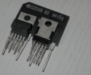
For example, this is on sale under the guise of LM1875 where I live.
Attachments
Only 15 V? Is this number correct?15V single supply psu , tda2040,
now it has worked for a week without problems.
And what can you say about sound quality?
......yes,only 15Vdc, because i used what i had on hand.
made a sim - at 4Vpp output with a 4ohm load(res) the transistors begin to conduct...
the sound quality was good, so i decided to go on......
now i have a psu with 28Vdc and listen to it.
if it works i will change resistors ( lower values) and booster transistors (switching types ,higher currents), because i saw a schematic in an old book for "electronic practice" where 0,68ohms and tip2955/tip3055 are used.
perhaps i will buy some bd9xx transistors.......
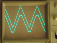
........so it worked with the 28Vdc supply (25VA transformer, 20Vac ; 8A bridge rectifier, 6800uF elcap) without problems.
with a 4 ohm load the psu volts go down to 24,5Vdc and the amp begins clipping (distorting) at 20Vpp output........
there are no crossover distortions on the o'scope or in the sim to see.........
i think the next step is to decrease the 1 ohm resistors to 0,47ohms (0,5ohm) -
this should give less losses and a better damping factor.
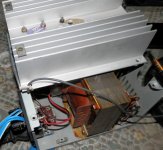
I also made a temporary test facility for verification, but I can not listen to this scheme at high volume yet. I can certainly use a resistor as a load, but that is not entirely correct.
mjf, how do you think, should I lower resistance of the resistors in power rails? After all the meaning of the scheme will be lost, we will more and more load the chip.
mjf, how do you think, should I lower resistance of the resistors in power rails? After all the meaning of the scheme will be lost, we will more and more load the chip.
Interesting
......if i disconnect the power transistors in the sim clipping begins at lower output levels.these boosters seem to have a positive influence........
I
mjf, how do you think, should I lower resistance of the resistors in power rails? After all the meaning of the scheme will be lost, we will more and more load the chip.
.......at high levels the tiny power opamp will have some "stress at work" (e.g. with low impedance speakers) and the booster transistors can deliver some extra current.
at lower levels (a few watt) the opamp doesnot need these helper transistors....
Now I see, it's my falt. You use TDA2040, and this chip more powerful than TDA2030.
More detais please. Which characteristics of transistors are important?0.82 - 1 Ohm should be optimal, depending on transistors used.
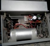
I've made this amplifier from the trash in order to hear whether this circuit sounds normal It's temporary. Soon I'll solder the second channel and find a suitable case.
The sound surprisingly is pretty nice. I can hear all the intonations of the singer's voice. Electric guitars that I especially like sound great. No hum, noise etc. The sound power is quite enough for a small room.
I don't have any equipment to check those aluminium caps, but I think they are dead. Then I plug off the amp from the electric system the sound immediately disappears. They are very old and the worst caps in the world- legendary Soviet K50-6 series So huge and only 2200 uF, 50 V. I'll replace them then.
And I will also reduce the resistance of the resistors from 1.5 to 1.2-1.0. Let at low volume only TDA sounds.
Now my amp's Gv is 12. Should I increase it?
It's temporary. Soon I'll solder the second channel and find a suitable case.The sound surprisingly is pretty nice. I can hear all the intonations of the singer's voice. Electric guitars that I especially like sound great. No hum, noise etc. The sound power is quite enough for a small room.
I don't have any equipment to check those aluminium caps, but I think they are dead. Then I plug off the amp from the electric system the sound immediately disappears. They are very old and the worst caps in the world- legendary Soviet K50-6 series
So huge and only 2200 uF, 50 V. I'll replace them then.And I will also reduce the resistance of the resistors from 1.5 to 1.2-1.0. Let at low volume only TDA sounds.
Now my amp's Gv is 12. Should I increase it?
Attachments
With transistors you have to look after their Hfe (gain) and the Vbe (usually 0.6-0.7V)
The resistor values I recommended (0,82 - 1 Ohm) will let the chip-amp "take" (very roughly) approx 0,7-0,9A of the output current, and transistors will take of the rest.
With 8 Ohm speakers, this means that the chip-amp will work "by itself" to roughly approx 4-6W peak power; and with 4 Ohm spkrs this would be 2-3W peak output power.
That should be "good enough" and somewhere in the ballpark for the "first Watt" imho.
 excellent work, and its good to know the basic design seems sound.
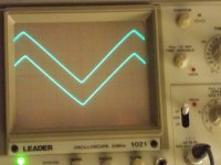
- Home
- Amplifiers
- Chip Amps
- TDA2030 with transistors