Just want to make sure this is how its done. I have a transformer that will be connected in series, so I won't have the center tap available like in the manual.
Brian, you might want to include such a diagram in your PDF, as I'm sure I wasn't the only green thumb that was a bit confused by all the connections.
PS: Thanks for everything!
Brian, you might want to include such a diagram in your PDF, as I'm sure I wasn't the only green thumb that was a bit confused by all the connections.
PS: Thanks for everything!
Attachments
Hybrid fourdoor said:Ok so everything else is ok though?
EDIT: This will work right? Changed the Trafo hookup
No.
Does your transformer have a CT secondary or dual secondaries?
No, you have more than just the transformer wiring wrong.
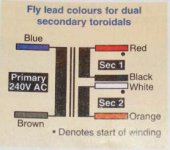
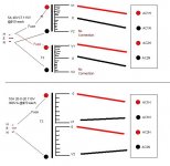
You will need a transformer with dual secondaries, that is a transformer with 4 output wires. In a catalogue it will be described as "secondary voltage 25 + 25" or similar. Here is a photo from a parts catalogue showing what we mean.
You will need a transformer with dual secondaries, that is a transformer with 4 output wires. In a catalogue it will be described as "secondary voltage 25 + 25" or similar. Here is a photo from a parts catalogue showing what we mean.
Attachments
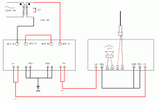
For the transformer to power board wiring, you will need to wire up one wire from secondary 1 to AC1 H and the other to AC1 N. From secondary 2 you will need to connect one wire to AC2 H and the other to AC2 N. Now you will need to wire the power supply to the amp board. Simply connect PG+ to PG+, V+ to V+, PG- to PG-, V- to V- .
To wire the rest of the amp board, OG (output ground) goes to your black speaker terminal. OUT goes to your red speaker terminal. IN (input) is from the centre of your input RCA connector. SG (signal ground) is from the outer connector of the input RCA. CHG (chassis ground) is wired to the earth (ground) point of your chassis. Make sure you connect your chassis earth to the earth lead of your mains wiring and you should be OK.
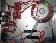
Here is a photo of what I have done. At the moment I am running 1 transformer and one power board per channel. If you are running 2 channels from the one power board you will see that Brian has set up 2 pads for each output, you will just wire up to the second channel exactly as described above from the second set of solder pads. Hope this makes sense and helps you out.
To wire the rest of the amp board, OG (output ground) goes to your black speaker terminal. OUT goes to your red speaker terminal. IN (input) is from the centre of your input RCA connector. SG (signal ground) is from the outer connector of the input RCA. CHG (chassis ground) is wired to the earth (ground) point of your chassis. Make sure you connect your chassis earth to the earth lead of your mains wiring and you should be OK.
Here is a photo of what I have done. At the moment I am running 1 transformer and one power board per channel. If you are running 2 channels from the one power board you will see that Brian has set up 2 pads for each output, you will just wire up to the second channel exactly as described above from the second set of solder pads. Hope this makes sense and helps you out.
Attachments

- Status
- This old topic is closed. If you want to reopen this topic, contact a moderator using the "Report Post" button.
- Home
- Amplifiers
- Chip Amps
- Hookup diagram of the BGT GroupBuy PCB....is this right??