Optimizing pcb routing for bridged amp
In order not to go further OT in sr2002's thread, I thought I'd move this to another thread.
So, I was laying out a pcb for a bpa200 inspired amplifier. Considering it's a bridged amp, what's the best way to lay out the power supply section ? Most of the circulating currents are in between the rails, not through the ground. Still, there are decoupling caps to take care of.
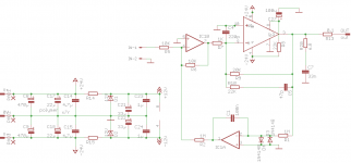
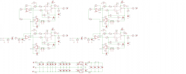
Would the following layout make sense ? It's a pcb for two lm3886, two pcb are required for a full amp, with a bridging adapter. The V- and V+ rails are overlapping (to easily daisy chain pcbs). When brought to the lm3886 (both on top layer), there is a local power groundplane (bottom layer) to which the decoupling caps connect. The low level signal section (buffer and servo) sits on another groundplane (top layer).
The schematic is for half the pcb.
In order not to go further OT in sr2002's thread, I thought I'd move this to another thread.
So, I was laying out a pcb for a bpa200 inspired amplifier. Considering it's a bridged amp, what's the best way to lay out the power supply section ? Most of the circulating currents are in between the rails, not through the ground. Still, there are decoupling caps to take care of.
Would the following layout make sense ? It's a pcb for two lm3886, two pcb are required for a full amp, with a bridging adapter. The V- and V+ rails are overlapping (to easily daisy chain pcbs). When brought to the lm3886 (both on top layer), there is a local power groundplane (bottom layer) to which the decoupling caps connect. The low level signal section (buffer and servo) sits on another groundplane (top layer).
The schematic is for half the pcb.
Attachments
Last edited:
Ok, let's follow the flow:
The current comes from the V+ rail, which means from the decoupling cap tied to the V+ next to lm3886 n°1. It goes through the output transistor and then into the load. From the load it goes into the output transistor of lm3886 n°2 and from there into the V- rail. Which means into the decoupling cap tied to V- next to lm3886 n°2.
To tie the loop, we need a short low impedance connection between the first cap and the second. Which is a local gnd line... or simply using a single cap rail to rail rather than two.
Which means my layout is all wrong.
yes, but where would be the fun in that ?
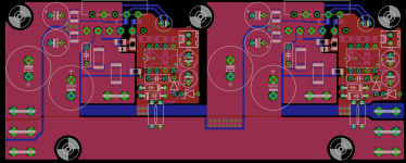
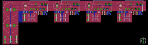
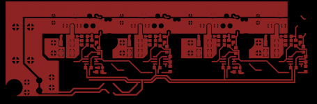
I think I can fit the servo quite easily in there. Here's a 16*5cm pcb with all 4 lm3886 onboard. Still a lot of place for opamps.
Decoupling is mostly rail to rail, except for 4.7uF x7r caps under the board near the lm3886 pins. The v+/v- rails are on top, the groundplane at the bottom.
I think I can fit the servo quite easily in there. Here's a 16*5cm pcb with all 4 lm3886 onboard. Still a lot of place for opamps.
Decoupling is mostly rail to rail, except for 4.7uF x7r caps under the board near the lm3886 pins. The v+/v- rails are on top, the groundplane at the bottom.
Attachments
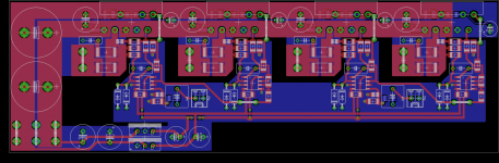
Almost there. I've still to shift things around a bit to make room for some mounting holes but the basics are there.
The pcb can either be a stereo BR100 or a mono BPA200 (by tying the input/output together). Since the decoupling is mostly rail to rail, I didn't make provision for parallel operation.
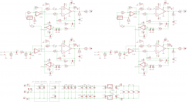
The overall scheme is quite simple. All the lm3886 are operating inverting. The dual opamp are serving two functions. One section of each is serving as servo. The other section is serving as buffer. Two opamps are setup as non inverting buffers to provide a high impedance input. Two opamps are inverting the signal for bridged operation.
The pcb can either be a stereo BR100 or a mono BPA200 (by tying the input/output together). Since the decoupling is mostly rail to rail, I didn't make provision for parallel operation.
The overall scheme is quite simple. All the lm3886 are operating inverting. The dual opamp are serving two functions. One section of each is serving as servo. The other section is serving as buffer. Two opamps are setup as non inverting buffers to provide a high impedance input. Two opamps are inverting the signal for bridged operation.
Attachments
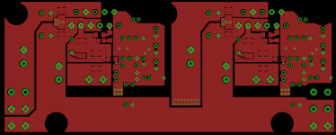
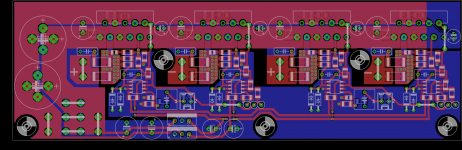
One of the problems of this design is the need for high current tracks. Even only two lm3886 in // can push at least 14A. And the lm3886 pins don't make it easy, especially as the area in between the pins and the edge of the pcb (where the lm3886 attach to the heatsink) is quite narrow.
One way to widen the tracks is to attach the lm3886 to a 4 or 5mm thick bar of aluminum. This can go above the pcb and that's some area reclaimed for more copper. As is, I've got almost 300mil wide tracks now.
One way to widen the tracks is to attach the lm3886 to a 4 or 5mm thick bar of aluminum. This can go above the pcb and that's some area reclaimed for more copper. As is, I've got almost 300mil wide tracks now.
Attachments
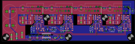
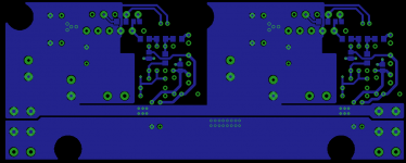
I had some more time to play with Eagle. The board can now accept a stereo pa100, a stereo br100 or a mono bpa200. To allow parallel operation, one just has to adapt the resistors around one of the input opamps.
By shifting the lm3886 output track to the bottom of the board, the power rails are a bit more uniform.
The only thing I'm not too happy about is the location of the return connectors needed for // operation.
By shifting the lm3886 output track to the bottom of the board, the power rails are a bit more uniform.
The only thing I'm not too happy about is the location of the return connectors needed for // operation.
Attachments
- Status
- This old topic is closed. If you want to reopen this topic, contact a moderator using the "Report Post" button.
- Home
- Amplifiers
- Chip Amps
- Optimizing pcb routing for bridged amp?