My Logitech Z-2300 unit suffers from an audible low frequency humming. My observations about the humming are as follows:
Upon googling further, I found a common problem in the Z-2300 is a subpar mechanical joint of two ground wires. See Logitech Z-2300 subwoofer hum solved! | YourITronics. I replaced the mechanical joint with a soldered joint, but unfortunately this did not mitigate the humming.
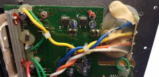
I then spend some time measuring the power supply circuit of the Z-2300 with my DMM but I couldn't find anything suspicious: mains voltage appeared over the primary coil, the secondary was at 40.2V AC and I measured 54.2V DC after the bridge rectifier. Measuring the rails for the MOSFETs, my DMM reported an initially high ripple on the DC voltage but after a while the reading would stabilize to less than 1V (note this was with no outputs connected).
I then proceeded to try and de-solder the output caps on the bridge rectifier (in order to measure their capacitance, I don't own a ESR meter) but have been unable to desolder them due to all the epoxy on the PCB. As the two big caps still look in good condition in the pictures linked below, I'm doubting whether they are causing the humming.
The similarly between the humming from the transformer and from the speakers leads me to believe the transformer might be the culprit? While reading on transformer humming, I typically read about mechanical humming. In this case the humming from the transformer sounds more electrical though. Is there anything I can try to determine whether the transformer is the culprit? Unfortunately I don't have access to a bench power supply, I only have a DMM (though it can read capacitance and conductance).
Finally, can anyone suggest any further steps for troubleshooting the issue?
Link to imgur album.
edit: replaced images with link to imgur.
- The humming comes from both satellite speakers and the woofer speaker. Though I'd say the humming from the satellite speakers is slightly louder.
- The humming is independent from the volume setting on the control remote
- The humming is present with and without an audio source connected to the 3.5mm input
- When disconnecting the satellite speakers and the woofer speaker, the humming is no longer audible. Though I can hear a similar humming (same pitch) originating from the toroidal power transformer, but it is much less audible.
- The humming remains audible when only the woofer is connected (with satellite speakers not connected) and when only the satellites are connected (with woofer speaker not connected).
- The humming was also present in my previous home.
Upon googling further, I found a common problem in the Z-2300 is a subpar mechanical joint of two ground wires. See Logitech Z-2300 subwoofer hum solved! | YourITronics. I replaced the mechanical joint with a soldered joint, but unfortunately this did not mitigate the humming.
I then spend some time measuring the power supply circuit of the Z-2300 with my DMM but I couldn't find anything suspicious: mains voltage appeared over the primary coil, the secondary was at 40.2V AC and I measured 54.2V DC after the bridge rectifier. Measuring the rails for the MOSFETs, my DMM reported an initially high ripple on the DC voltage but after a while the reading would stabilize to less than 1V (note this was with no outputs connected).
I then proceeded to try and de-solder the output caps on the bridge rectifier (in order to measure their capacitance, I don't own a ESR meter) but have been unable to desolder them due to all the epoxy on the PCB. As the two big caps still look in good condition in the pictures linked below, I'm doubting whether they are causing the humming.
The similarly between the humming from the transformer and from the speakers leads me to believe the transformer might be the culprit? While reading on transformer humming, I typically read about mechanical humming. In this case the humming from the transformer sounds more electrical though. Is there anything I can try to determine whether the transformer is the culprit? Unfortunately I don't have access to a bench power supply, I only have a DMM (though it can read capacitance and conductance).
Finally, can anyone suggest any further steps for troubleshooting the issue?
Link to imgur album.
edit: replaced images with link to imgur.
Last edited:
A 2pin mains plug tells you and us that you have a double insulated product that should have a double concentric square symbol on the labeling confirming this.Upon researching this issue on google, the most probable culprit would seem to be a ground loop. Note that the unit does not have a ground terminal (it uses a two terminal plug).
This is a ClassII product. DO NOT tamper with the existing mains connections !!!!!!
The third pin fitted to ClassI products is for SAFETY only. It has nothing to do with audio performance.
Again with ClassI products, DO NOT tamper with the existing mains connections.
Last edited:
I am surprised to see 10000uF (10mF) 35V capacitors in there. That points to NOT penny pinching. A good sign that they have tried to do things right.
But you have used a remote server to locate your pics and they automatically download the full enormous data each time we log onto your page.
Please use the Forum's Attach process. And delete the enormous files.
But you have used a remote server to locate your pics and they automatically download the full enormous data each time we log onto your page.
Please use the Forum's Attach process. And delete the enormous files.
Last edited:
No.Samxon caps are (very) low quality.
I would replace or at least check them.
do not replace anything until after you find they are faulty.
Measure the Vripple at the smoothing capacitors. That will tell you a lot about how good, or bad they are. Armed with that information you can then make an informed decision on whether they are faulty and need replacement.
BTW,
There is a small cheap ESR meter described in this Forum. You can test Vripple (power ON) and ESR (power OFF) while the capacitors are still in circuit.
I don't believe you.The low frequency humming comes from the low quality PSU of your speakers.
Floris is probably correct in concluding (without much evidence) there is likely to be a wiring error.
Thank you everyone for your input, I've performed some additional measurements of the DC smoothing.
I have a fairly decent DMM which can measure ripple voltage on a DC voltage, though I doubt how to interpret its readings. Measuring the FET rails, it initially reports a large ripple voltage on rails but then the readings gradually lower until they are less than a volt and then they stabilize at this level (this decay appears exponential). This is confirmed by switching my DMM to DC voltage where it shows 54.17V across the power rails with a variation of 0.5V. This amounts to less than 1% of ripple. Is this problematic for audio amplifiers?
Measuring the DC voltage directly on the smoothing caps, my DMM reads 27.2V with +-2.5V variation for cap 1 and 27.3V with 2.6V variation for cap 2. When measuring over both capacitors I get the same reading as on the power rails of the mosfet; so 0.5V variation on 54.2V.
I'll try again to desolder the caps in order to measure their capacitance and I might look into the ESR meter if it's not too difficult to build.
@Andrew: you think there might be a wiring issue? Do you mean a component might not be probably grounded and that this could be the issue? I'm still thinking the toroidal transformer might be the culprit.
I redid the measurements, as I misread the output from my DMM in my previous post:
Smoothing cap1: 27.4V DC, 0.05V AC
Smoothing cap2: 27.4V DC, 0.05V AC
Both caps: 55V DC, 0.1V AC
FET rail: 54.8V DC, 0.1V AC.
Strangely enough, repeating the measurements now (I just repowered the system, ok the FETs are running a little hot but nothing extreme) and all DC voltages are 0.6V lower ?
Smoothing cap1: 27.4V DC, 0.05V AC
Smoothing cap2: 27.4V DC, 0.05V AC
Both caps: 55V DC, 0.1V AC
FET rail: 54.8V DC, 0.1V AC.
Strangely enough, repeating the measurements now (I just repowered the system, ok the FETs are running a little hot but nothing extreme) and all DC voltages are 0.6V lower ?
Yes, that was the first thing I tried. Unfortunately without success.
I finally managed to desolder the caps and measured their capacitance: 11.05mF and 11.4mF so they seem fine. It is possible that they have failed without losing capacitance but with e.g. an increase in ESR?
I don't really know what to try next. Any suggestions? Maybe get/make an ESR meter (but my hunch tells me the smoothing caps are fine) or try excluding at the transformer. Maybe I can try to supply DC voltage directly to the smoothing caps in order to try and eliminate everything beween the mains input and the smoothing caps (transfo, rectifier diodes, mains input)? I'd have to get another power supply for this though.
0.05Vac is very low for Vripple on a high bias mosFET amplifier.I redid the measurements, as I misread the output from my DMM in my previous post:
Smoothing cap1: 27.4V DC, 0.05V AC
Smoothing cap2: 27.4V DC, 0.05V AC
Both caps: 55V DC, 0.1V AC
FET rail: 54.8V DC, 0.1V AC.
Strangely enough, repeating the measurements now (I just repowered the system, ok the FETs are running a little hot but nothing extreme) and all DC voltages are 0.6V lower ?
What scale are you using? 19.99Vac, or 1.999Vac, or 199.9mVac?
You can't measure the Least Significant Bit (LSB) with any degree of accuracy.
Your DMM needs a resolution at least ten times lower than what you are trying to measure. For 50mVac I would be using the 199.9mVac scale. But I start up at a much higher scale and only AFTER I have proved to myself that going down to the next scale won't damage the meter do I switch lower.
Some Digital Voltmeters can measure low AC voltages while there is a high DC voltage present.
Others either read incorrectly, or simply give up completely. These can be adapted by adding a DC blocking capacitor into the measuring route. The capacitor has to be sized to pass the ripple fundamental. Use Freq=1/{2 Pi R C}
The bias current probably changes as the amplifier warms up.
That changes the load on the PSU.
The output voltage drops as bias increases and conversely the Vripple increases as bias increases.
Last edited:
@Andrew: I used autoranging while my DMM was set to measure AC and DC voltage in the 1V mode. Perhaps I should have tried the mV AC mode of the DMM for measuring the ripple.
However, upon resoldering the capacitors and re-installing the PCB onto the woofer back plate I noticed that the humming has disappeared from the speakers! This was yesterday evening and today it hasn't returned so far. I'm hoping it'll stay good for now. The transformer still humms, but this is almost inaudible as I placed the woofer with the transfo in a corner of the room.
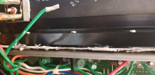
I can only guess what might have been the cause of the humming at this point, clearly the transfo was not the culprit. My best guess would be the grounding from either the PCB to the chassis heatsink or from the FETs to the heatsink (I reinstalled the bar pushing the FETs on the heatsink) . I noticed there are small strips of plastic between the heatstinks of the FETs and the chassis heatsink. While I don't know their function, I realigned a number of these strips. But I don't know what solved the humming, all I can say is I'm relieved it's gone!") Thanks everyone!
Thanks everyone!
However, upon resoldering the capacitors and re-installing the PCB onto the woofer back plate I noticed that the humming has disappeared from the speakers! This was yesterday evening and today it hasn't returned so far. I'm hoping it'll stay good for now. The transformer still humms, but this is almost inaudible as I placed the woofer with the transfo in a corner of the room.
I can only guess what might have been the cause of the humming at this point, clearly the transfo was not the culprit. My best guess would be the grounding from either the PCB to the chassis heatsink or from the FETs to the heatsink (I reinstalled the bar pushing the FETs on the heatsink) . I noticed there are small strips of plastic between the heatstinks of the FETs and the chassis heatsink. While I don't know their function, I realigned a number of these strips. But I don't know what solved the humming, all I can say is I'm relieved it's gone!
Thanks everyone!The Z-2300 has a design flaw. The chassis should be earthed next to the signal input only. This is done by two screws holding the PCB. (The two nuts on the side near to the input).
However, the PCB is also grounded with a green wire to the cooling assembly. (the wire that is connected on the back of the amplifier assembly). To get rid of the hum you can tighten the screws on the PCB to restore good contact, cut the green wire, or both. I did both and the hum completely disappeared!
Be aware that when you cut the green wire and the insulation between one of the amplifier units on the cooling rail fails, a large DC current will flow though the PCB. This can cause fire.
Attachments
- Status
- This old topic is closed. If you want to reopen this topic, contact a moderator using the "Report Post" button.
- Home
- Amplifiers
- Chip Amps
- Troubleshooting low frequency humming in PC speaker set