Have we got the right versions here... whatever, and surprisingly, both seem to give identical responses. Load the two images into a photo viewer and switch between them.
Thank you for simulation.
In that case I will run bass boost before LPF to avoid possibility of clipping because I run bass boost at 12v and LPF on +-18.
There is something in the simulation I am not happy with.
Does yours sound all right ? or does it distort or clip under certain conditions ?
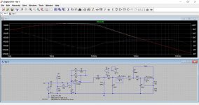
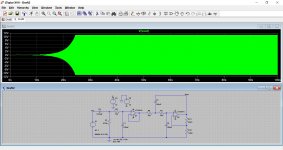
The problem seems to occur when a critical gain factor is reached and yet this doesn't seem to dramatically affect the simulation of the overall response.
This is with just 10 millivolts peak applied. The circuit breaks into oscillation.
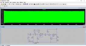
The feedback gain setting resistor is then reduced from 10k to 5k and all is normal.
Does yours sound all right ? or does it distort or clip under certain conditions ?
The problem seems to occur when a critical gain factor is reached and yet this doesn't seem to dramatically affect the simulation of the overall response.
This is with just 10 millivolts peak applied. The circuit breaks into oscillation.
The feedback gain setting resistor is then reduced from 10k to 5k and all is normal.
Attachments
Mooly,
the final two resistors setting the gain of the equal component value filter set the Q of the filter.
Setting the Q too high is the problem.
One should be setting the Q of the filter to a value that gives the Shape of the filter.
Gain of the signal is set elsewhere, as you surmised.
Here is Ti explanation.
Section 3 applies to the LPF sch shown. Note 3.1 and 3.4
Attachments
Last edited:
We look to be half way toward a Wien Bridge type oscillator with the gain factor chosen.
It needs a rethink on gain. If you need gain then applying it to the other stages will be the way forward.
One for tomorrow")
No, on the bass boost I set the gain of 2 (6dB) with 10k - 10k resistors. On original design it was 1k - 10k gain of 11. With gain of 11 it was distorting like hell. I don`t know why author of original bass boost circuit set gain so high. Maybe he used alot lower input signal or something.
Or is gain setted differently for NE5534 (and compatible IC`s) than for NE5532?
Last edited:
Mooly,
the final two resistors setting the gain of the equal component value filter set the Q of the filter.
Setting the Q too high is the problem.
One should be setting the Q of the filter to a value that gives the Shape of the filter.
Gain of the signal is set elsewhere, as you surmised.
Here is Ti explanation.
Section 3 applies to the LPF sch shown. Note 3.1 and 3.4
Thanks Andrew. The details show that I overstepped the gain at which the combined phase shifts take the stage into positive feedback and oscillation.
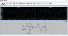
The magic figure for a Wein oscillator is also a loop gain of 3 and so I tried plugging those values for gain into the circuit. Here we have a 1999 and 1000 ohm feedback network (gain of 2.999) and a 2001 and 1000 ohm (gain of 3.001). There was a 10mv excitation voltage applied to the input in each case.
No, on the bass boost I set the gain of 2 (6dB) with 10k - 10k resistors. On original design it was 1k - 10k gain of 11. With gain of 11 it was distorting like hell. I don`t know why author of original bass boost circuit set gain so high. Maybe he used alot lower input signal or something.
Or is gain setted differently for NE5534 (and compatible IC`s) than for NE5532?
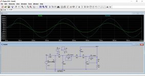
I'll change your circuit for a gain of 12db by applying the gain elsewhere.
Attachments
You need to remove the feedback network and connect the opamp as shown. Then test it and see if you have enough gain for your application. If not then we can add gain around the middle opamp.
I don't understand how should problem show up?
I would also like to use LPF without bass boost.
You can set gain separate from Q if you use 3 low-value resistors in the NFB....oscillator with the gain factor chosen.
It needs a rethink on gain....
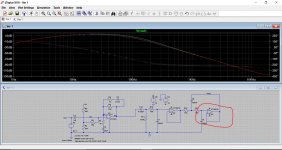
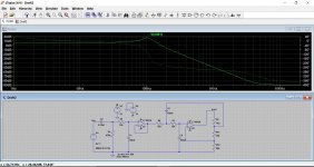
Your stimulator will tell you the "error of this way". Eyeballing, I think it goes 30dB down (15K/560r) and then eases-off one pole. For most audio purposes this is good-enough.
Yes, gain in the middle buffer works sure.
Attachments
Last edited:
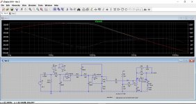
Interesting, thanks. This is the response with your suggested values. Doubling C5 removes the peak and shifts the turnover frequency down a little.
You could play around with this for hours to get what you want. Here is the original file if anyone wants to play.
You could play around with this for hours to get what you want. Here is the original file if anyone wants to play.
Attachments
 if you are happy, we are happy.
- Status
- This old topic is closed. If you want to reopen this topic, contact a moderator using the "Report Post" button.
- Home
- Amplifiers
- Chip Amps
- Making preamplifier...