Assume the gate needs 6V.
63% of 48V = 30V. That's the voltage that will have charged up the capacitor that does not leak when 1*RC has expired.
6V is ~20% of 30V so you are looking for ~ 20% of the RC as your timer value.
Thus for 5seconds delay you need an RC of 5seconds/20% = 25seconds.
2M2 & 11uF = 24seconds
You could use 10uF low leakage electro, or if you can tolerate a shorter delay use a 4u7F MKT.
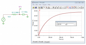
Let's straighten out the math. The capacitor voltage increases exponentially over time starting at t=0, which is when the power supply is turned on. The capacitor voltage can be calculated from the following equation:
Vc = Vs*(1-e^(-t/RC)),
where Vc is the voltage across the capacitor vs time and Vs is the supply voltage.
Solving for t yields:
t = -ln((Vs-Vc)/Vs)*R*C
Plugging your values of Vs=48; Vc=6; R=2.2M; C=100u results in:
t = 29.38 seconds
You can verify this using your favourite spice simulator.
Tom
Attachments
Last edited:
I am glad you are good at the maths required.
I am only good with simpler arithmetic.
Thus I have often used approximations that get confirmed, or otherwise, during testing.
Can you provide a similar non approximation set of formulae that allow for calculating a time delay when the electrolytic leaks?
I am only good with simpler arithmetic.
Thus I have often used approximations that get confirmed, or otherwise, during testing.
Can you provide a similar non approximation set of formulae that allow for calculating a time delay when the electrolytic leaks?
Last edited:
While I do appreciate the concerns around the delay circuitry, they don't bother me as much right now as the concerns Tomchr raised around grounding and decoupling in post #4. I would really, really appreciate if they were made clearer.
Thanks for any clarification on this.")
Thanks for any clarification on this.
The electrolytic leakage current will seriously lengthen the time delay and may even prevent triggering.
So you're saying that the leakage current is enough to cause (48-6) = 42 V drop across 2.2 MΩ? That would be 42/2.2E6 = 19 uA. Which electrolytic caps are you aware of that leak that much? I'm not aware of any...
While I do appreciate the concerns around the delay circuitry, they don't bother me as much right now as the concerns Tomchr raised around grounding and decoupling in post #4. I would really, really appreciate if they were made clearer.
I suggest reading my Taming the LM3886 article series: Taming the LM3886 Chip Amplifier
You can ignore the page on Stability as you have that covered in your design already. Also, that section is in serious need of an update.
Tom
Tom: I've read those pages a dozen times. My point is that I just don't get what's the problem here.
Wrt decoupling, I can hardly put the decoupling caps closer and I use the exact same caps you suggest in your article.
Wrt grounding, the signal section has its own groundplane, connecting to power ground at the output.
So what's wrong exactly?
Wrt decoupling, I can hardly put the decoupling caps closer and I use the exact same caps you suggest in your article.
Wrt grounding, the signal section has its own groundplane, connecting to power ground at the output.
So what's wrong exactly?
if one takes a fairly usual leakage value from the manufacturers' datasheetsSo you're saying that the leakage current is enough to cause (48-6) = 42 V drop across 2.2 MΩ? That would be 42/2.2E6 = 19 uA. Which electrolytic caps are you aware of that leak that much? I'm not aware of any... ..........
then we find that leakage should drop to less than the specified value within 2minutes.
Ileakage <= 0.003CV
for a 100uF charged to 48V that would be >14uA
the 2M2 with 48Vdc applied will initially pass 21.8uA and this falls slowly to 20uA when the the charge has reached 4Vdc
If half of this charging current leaks through the capacitor, the capacitor effectively charges up half as quickly.
That was a worst case because initially the capacitor has very low voltage applied.
It is for this and other reasons I suggest that polar electrolytics be slowly reformed BEFORE they are fitted to a circuit.
I find that slow reforming can reduce leakage to << 1% of specified 2minute values and get there almost instantaneously.
This becomes even more important in speaker protection filters where slow, or non-triggering could result in damage. Here the capacitors lie dormant possibly for years and initial leakage could/will prevent the trigger action, just when really required.
That's why I much prefer an MKT. For timers, try to scale values such that reasonable MKT values are practical.
Last edited:
Old ones. I'm working on a 1980 organ that thumps at turn on because Allen used an electrolytic 100 uf capacitor in the timing circuit, and the "serviceman" bypassed the timing module to provide instant 120 vac to the amps. I haven't changed it yet because a lot of other things are broken, like one amp & one speaker, and the DC power supplies & boards are chock full of 37 year old ecaps just like the ones that failed in the amps.Which electrolytic caps are you aware of that leak that much? I'm not aware of any...
Tom
I've used a ceramic 1 uf cap in power up reset circuits since 1976 when I designed boards for JSC MSC. Then I had to use an exotic 96S02 IC to sense a 1 megohm pull up circuit, but now nfets are $.38 and free in junk TV's, there is no reason to use any electrolytic in a timer circuit. If 00940's new circuit uses a plastic film 4.7 uf cap or the $5 ceramic version, he should be fine.
Thanks 00940 for doing this IMHO, Most protection circuits have a dozen parts if fet or a metal contact relay not rated to break 200A DC current. I don't connect $600 speakers to any transistor without one. A series capacitor for protection is stupid proof for 20 years anyway. The layout in the lm3886 datasheet perhaps is not experience tested. If you provide gerber files when done, or sell boards, it would be nice.
Last edited:
Tom: I've read those pages a dozen times. My point is that I just don't get what's the problem here.
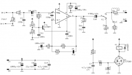
Sorry. I mistook your mute cap for the bypass cap. I see you have the three bypass caps in the middle of the schematic, connected by label. No problem.
Tom
Old ones. I'm working on a 1980 organ that thumps at turn on because Allen used an electrolytic 100 uf capacitor in the timing circuit, and the "serviceman" bypassed the timing module to provide instant 120 vac to the amps.
Sounds like a good argument to stay away from old electrolytics then.
I looked up the one I use for the mute cap (Panasonic P/N: EEU-EB1A101S). That cap is nothing special and probably representative of a cheap electrolytic cap. It's rated at 0.01 CV or 3 uA, whichever is greater. So you'll get a few uA of leakage. That's larger than I expected. Live and learn.
Thanks 00940 for doing this IMHO, Most protection circuits have a dozen parts if fet or a metal contact relay not rated to break 200A DC current. I don't connect $600 speakers to any transistor without one. A series capacitor for protection is stupid proof for 20 years anyway. The layout in the lm3886 datasheet perhaps is not experience tested. If you provide gerber files when done, or sell boards, it would be nice.
Yeah. The series cap will prevent DC from flowing ... until it shorts out. If you're going through the trouble of putting in a relay and delayed turn-on, you might as well add the couple of transistors needed to provide DC protection as well.
Tom
Thanks Tom for clearing things up. Sorry for being insistant on this. I"ve got to say that the onboard relay and the big output capacitor don't help to keep the layout as tight as I'd like.
The safety of the output capacitor is a good question. My first projects in diy were mostly headphones amplifiers, in particular OTL tubes amps. It is common for those amps to only have a cap in between high DC voltage and your headphones. Safety concerns were usually dismissed by a "caps don't fail short". There are many kits on the market with such output capacitors (let's just name the bottlehead crack as an example). In such cases, a failure could be much worse than just a burnt out speaker.
I could redesign a bit the board to add full DC protection. After all, the big elements are already there and it wouldn't cost much more.
I will post the eagle files when I'm done. I might have a few extra board to sell at cost when I order the pcb but it's not a commercial venture for me.
The mute circuit works fine. It regulates the output of the IC to the voltage on the GND pin. If that voltage is not the same as the speaker negative terminal voltage, you'll get a plop in the speaker when the IC un-mutes. Also, the output cap needs to charge on start-up, which will cause a pretty significant plop in the speaker, so adding an anti-plop relay is a good idea.
Personally, I use the LM3886 in a split supply (i.e. Vsupply = ±V) scenario. I have never had an issue with turn-on plop caused by the LM3886.
The mute circuit is useless for DC protection. If you need that, you'll be adding a relay. In that case, you might as well delay the turn-on of the speaker as well. For a single supply system, I'd definitely encourage the use of a relay, both for DC protection and for anti-plop.
Tom
I built a single supply headphone amplifier that uses a "slow start" circuit and no protection relay. Basically it slowly raises the bias voltage. It takes about two seconds to bias. I used clamping diodes to discharge the output capacitor on shutdown. I also used them on the input.
There's a click on startup and a thump on shutdown, but no big thumps or loud clicks. It met the design objectives, which were to greatly mitigate the click/thump.
I don't know if this would work very well with the 3886, but I thought I'd put it out there for discussion.
There's a click on startup and a thump on shutdown, but no big thumps or loud clicks. It met the design objectives, which were to greatly mitigate the click/thump.
I don't know if this would work very well with the 3886, but I thought I'd put it out there for discussion.
A big c11 would pretty much achieve that.
Actually, not necessarily. You'd need C11 to be large and the charging time for the mute circuit (so C27*R8) to be significantly longer than C11*(R2||R5). Recall that once the IC un-mutes, the voltage on its ground pin becomes irrelevant. See: LM3886 chip amp grounding.
I'm curious why you don't take the GND reference for the input on the emitter of T1, though.
Speaking of T1: I would add a load from its emitter to GND. Emitter followers are not fond of light loads and the only load it "sees" is some fraction of a base current from the LM3886.
Tom
I don't know if this would work very well with the 3886, but I thought I'd put it out there for discussion.
It would probably work. You just have to balance the mute time constant with the bias time constant, which may or may not be worthwhile to you.
You'll also have to give up any requirements of "no thump" and accept "some thump".
Nothing wrong with either, just pointing out the tradeoffs.
Tom
- Status
- This old topic is closed. If you want to reopen this topic, contact a moderator using the "Report Post" button.
- Home
- Amplifiers
- Chip Amps
- Single supply LM3886 layout